0 controls (cont'd) – Reznor RDF Unit Installation Manual User Manual
Page 20
I-RDF, PN148384R5, Page 20
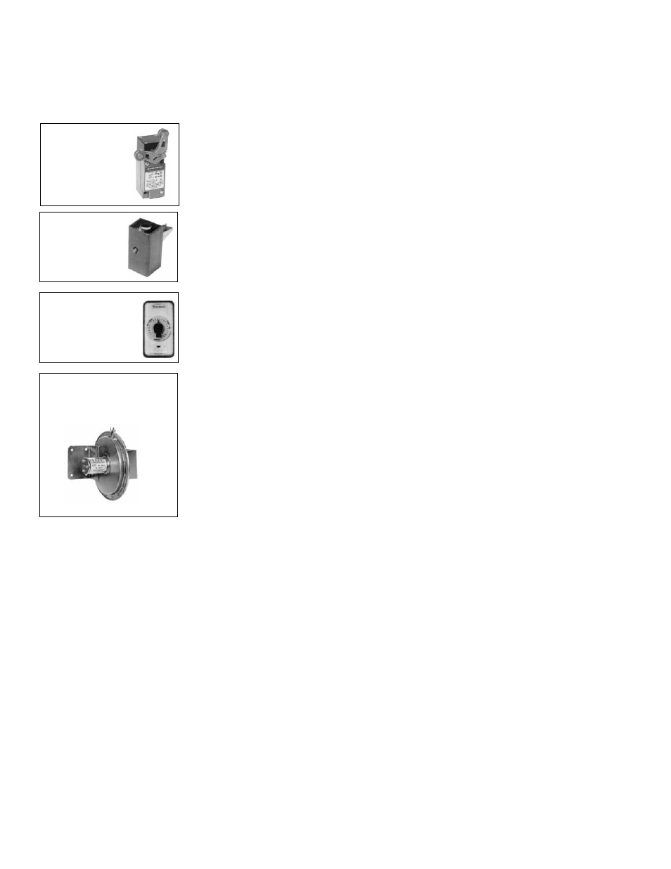
FIGURE 20 -
Optional
Door Switch
FIGURE 22 -
Optional
Potentiometer
FIGURE 23 -
Pressure Null
Switch
FIGURE 21 -
Optional
Firestat
8.0 Controls
(cont'd)
Discharge Temperature Low Limit (Option BE2) -
If the system has an
optional low limit switch for discharge temperature (freezestat), the control is in the
blower section electrical box. The sensing bulb must be field-mounted in the blower
discharge duct connector. Uncoil the control and extend the bulb to the blower
discharge, being careful to not interfere with any mechanical parts. Use the bulb holder
provided and mount the sensor according to the manufacturer's instructions.
Door Switch (Option BX1) -
If the system is to be used as an overhead door
heater, an optional door switch (Option BX1) must be installed. The function of the
switch is to energize and interlock the system when an outside overhead door reaches
approximately 80% of full open travel. The switch will de-energize the system when
the overhead door closes approximately 20%. Follow the installation instructions in the
door switch option package and the wiring diagram.
Firestat (Option BD2) -
If the system has an optional firestat, the control is factory
installed in the heated airstream so that the sensor can be extended into the duct. The
firestat requires manual reset and is installed in an accessible location.
Optional Potentiometer (applies to systems with Air Control Option
AR19 for makeup air only or AR22 for outside and recirculation air)
-
If the system includes Air Control Option AR19, the discharge damper is controlled
by a manually set potentiometer. If the system includes Air Control Option AR22, the
potentiometer controls the return air damper. The potentiometer is shipped loose in the
control compartment, or if a remote console is ordered, it is mounted on the console.
Follow the wiring diagram to connect the potentiometer.
Optional Pressure Null Switch (applies to systems with Air
Control Option AR20 for makeup air only or AR23 for outside and
recirculation air) -
If the system includes Air Control Option AR20, the discharge
damper is controlled by a pressure null switch. If the system includes Air Control
Option AR23, the pressure null switch controls the return air damper. The pressure null
switch is shipped in the control cabinet. Refer to the following paragraphs and to the
manufacturer's installation instructions to install and connect this switch.
The pressure null switch is Dwyer #1460-0 with a range of .01-.12" w.c. The pressure
null switch is a diaphragm operated differential pressure switch used in makeup air
applications to control building pressure. It maintains a selected positive or negative
pressure setpoint by changing the amount of outside air being introduced to the build-
ing through the modulating outside air dampers. As more pressure is required in the
building, the pressure null switch activates the damper motor driving the outside air
damper towards the full open position and the recirculated air damper towards the
closed position. Conversely, as less pressure is required, the switch drives the damp-
ers in the opposite direction.
Installation
Instructions for
Pressure Null Switch
(See FIGURE 24):
Select an indoor location free from excessive vibration where oil or water will not drip
on the switch and where ambient temperature will be within a range of -30°F (dry air)
to 110°F.
Mount the switch with the diaphragm in a vertical plane. The switch is position sensi-
tive and is calibrated to operate properly when the diaphragm is vertical. Mount switch
securely.
Connect the pressure taps on the top of the switch to sources of air pressure differen-
tial. Metal tubing with 1/4" O.D. is recommended but any tubing which will not unduly
restrict the airflow can be used. To maintain a positive building pressure, vent the low
pressure tap to the outdoors and allow the high pressure tap to monitor building pres-
sure. To maintain a negative building pressure, reverse the functions of the high and
low pressure taps. In either case, be sure that the outdoor vent is protected from the
wind and screened from insects.
Adjustment of the Switch - The "high" actuation point of the null switch is indicated on
a calibrated scale secured to the transparent range screw enclosure. Building pressure
is set by turning the adjustment screw. The "low" actuation point is set by adjusting the
span on the null by turning the span adjustment screw. The span range is .01 - .03" w.c.