0 mounting (cont'd), 4 mounting on a roof curb (cont'd), Roof curb installation instructions (cont'd) – Reznor RDF Unit Installation Manual User Manual
Page 8
I-RDF, PN148384R5, Page 8
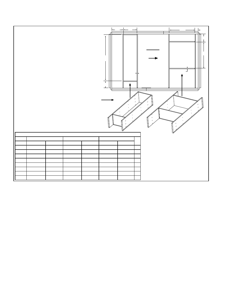
Airflow
Assembled Dividers for Optional
Return Air Ductwork in the Roof Curb
Field-supplied ductwork may be either
dropped in from the top resting on
the top flange or be attached to the bottom
flange, using the dividers as ductwork.
Bottom
Discharge
Supply Air
Opening
(A x B)
Return
Air
Opening
(E x F)
A
C
B
D
E
F
G
H
3/4 (19)
3/4 (19)
Top View
FIGURE 6 - Divider Locations for
Bottom Ductwork Openings
NOTES:
• Drawing is not proportional for all sizes.
• 3/4" (19mm) measurement is the width of the
flanges where the roof curb mates with the
heater. Flange surface must be sealed.
• When cutting duct openings in the roof, cut
opening(s) 1” (25mm) larger than duct size
opening for installation clearance.
5.0 Mounting
(cont'd)
5.4 Mounting on a Roof Curb (cont'd)
Roof Curb Duct Opening Dimensions (± 1/8" or 3mm)
Sizes 1-20, 1-40, 1-50, 1-65
2-80, 2-120
3-180, 3-260
inches
mm
inches
mm
inches
mm
A
23-11/32
593
28-13/32
722
38
965
A
B
20-1/8
511
28-11/32
720
38
965
B
C
5
127
13-15/32
342
11-19/32
294
C
D
10-1/4
260
7
178
4-5/8
17
D
E
25-1/2
648
54-11/16
1389
66-3/4
1695
E
F
11-1/2
292
17-23/32
432
20-1/16
510
F
G
11-15/32
291
8
203
10-15/32
266
G
H
11-1/32
280
11-3/32
282
17-1/4
438
H
3. If the system has a bottom discharge and/or a return air inlet, use the sheetmetal
screws to sub-assemble the dividers. Refer to the dimensions in
FIGURE 6 to
appropriately position the roof curb dividers to create the needed duct opening
flanges. Attach the dividers to the roof curb with sheetmetal screws.
NOTE: If the
system does not have a bottom discharge and/or a return air opening, the dividers
for an opening that is not going to be used may be installed but are not required.
4. Check the assembly for squareness. The curb must be adjusted so that the
diagonal measurements are equal within a tolerance of ± 1/8".
5. Level the roof curb. To ensure a good weatherproof seal between the unit curb
cap and the roof curb, the roof curb must be leveled in both directions with no twist
end to end. Shim as required and secure curb to the roof deck before installing
flashing.
6. Install field-supplied flashing.
7. Before placing the RDF unit on the curb, apply furnished 1/4" x 1-1/4" foam sealant
tape to the top perimeter surface of the curb, making good butt joints at corners.
The sealant tape must be applied to the curb rails to prevent water leakage into
the curb area due to blown rain and capillary action.
Also place the foam sealant tape on the perimeter of the top surface of the duct
opening(s), being sure to make good butt joints at corners. If installing ductwork
from the top, it is recommended that tape be put on again after the ductwork is
"dropped in", sealing below and above the duct flanges.
Roof Curb Installation Instructions (cont'd)