Assemble and install support legs, Step 2a - sub-assemble legs, Step 2b - install support legs – Reznor RDF Unit Installation Manual User Manual
Page 13
I-RDF, PN148384R5, Page 13
Top Filter Channel
Bottom
Filter
Channel
Top
Blockoff
Plate
Bottom
Blockoff
Plate
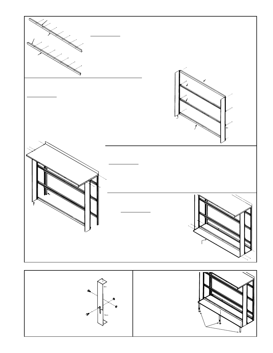
Step 1 B - Sub-assemble Top and Bottom Filter Channels and
Filter Blockoff Plates (AS6 & AS7)
Parts Required - Top and bottom filter channel; top and bottom filter blockoff
plates; and 14 screws (1/2" long)
Assemble the top blockoff plate and the top filter channel being sure the filter
channel groove is on the same side as the 90° bend in the blockoff plate but
directed away from it. Use seven screws to attach the top blockoff plate to the
top filter channel. Repeat the process with the bottom filter channel and bottom
blockoff plate.
Top Filter Channel with
Blockoff Plate
(assembled in 1B)
Center Channel
Assy
P/N 91578
Intermediate
Cabinet Post
Bottom Filter Channel
with Blockoff Plate
(assembled in 1B)
P/N 91578
Intermediate
Cabinet Post
Center Channel
Assy
Step 1C - Assemble Outer Side of Filter Rack
(Options AS6 and AS7 only)
Parts Required - Two intermediate posts; two remaining pre-
assembled center filter channels; the top and bottom filter
channel/blockoff plate assemblies form Step 1B; and 12
sheetmetal screws (1/2" long)
For 1" filters (Option AS6), attach the channel assemblies to the
holes closest to the inside of the intermediate posts.
For 2" filters (Option AS7), attach the channel assemblies to the
holes closest to the outside edge of the posts.
P/N 91575 T
op of Inlet
Hood Cabinet Section
Intermediate
Post
Corner
Post
Intermediate
Post
Corner
Post
Step 1D - Attach Cabinet Section To Corner Posts and
Intermediate Posts (Options AS2, AS6, AS7)
Parts Required - Cabinet top; the two corner cabinet posts (if inlet hood
with filters, posts will be sub-assembled to filter channels - Step 1A) (if
AS2 with no filters, ignore illustrated filter rack); the two intermediate
cabinet posts (if inlet hood with filters, posts will be sub-assembled to filter
channels - Step 1C); and six 1/2" long sheetmetal screws.
Attach cabinet section top to the four posts as illustrated.
Step 1E - Attach Cabinet
Section Bottom
Parts Required - Subassembly
from Step 1D; cabinet section
bottom; and six 1/2" sheetmetal
screws.
Position the cabinet section
bottom to the inside of the
four posts (corners). Attach as
illustrated.
P/N 91567
Bottom of Hood
Cabinet Section
2. Assemble and Install Support Legs
P/N 91581,
Support
Leg Half
P/N 91581,
Support
Leg Half
Step 2A - Sub-assemble Legs
Attach legs
at holes in
bottom.
Step 2B - Install
Support Legs
Parts Required - Three
sub-assembled legs and
three 3/4" sheetmetal
screws
Attach leg assemblies to
cabinet bottom.
Parts Required - Six support
leg halves and six 5/8" bolts
and nuts
Assemble support legs as
illustrated. Adjust legs to
shortest length and tighten
bolts finger tight. Length of
supports will be re-adjusted
to suit the application after
cabinet is installed.
FIGURE 11B
FIGURE 11C
FIGURE 11D
FIGURE 11E
FIGURE 11F
FIGURE 11G