Reznor RDF Unit Installation Manual User Manual
Page 21
I-RDF, PN148384R5, Page 21
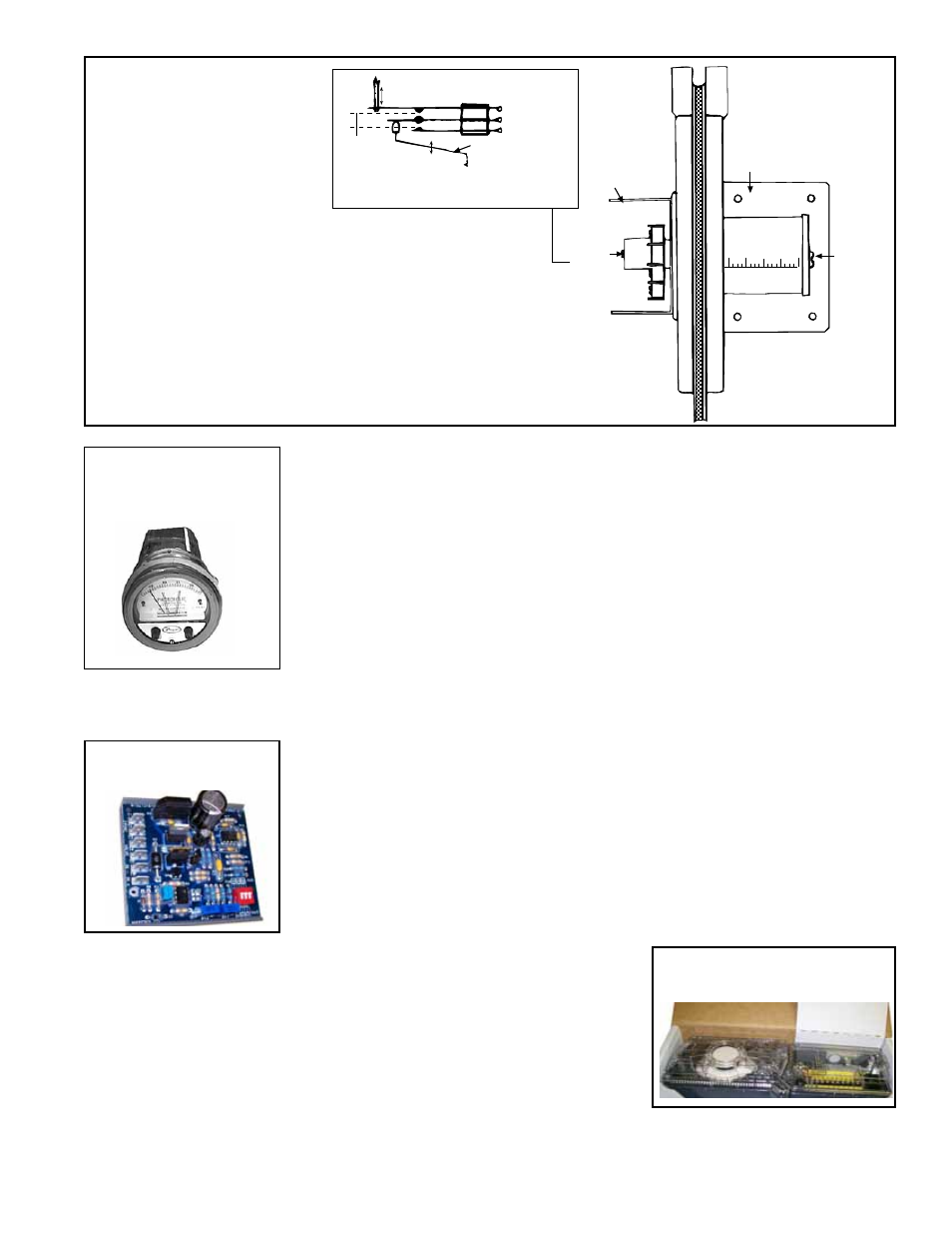
Switching action in the pressure
null switch
Electric Box
Span
Adjust
Screw
Mounting Plate
Pressure Taps
Low
High
Pressure
Adjust
Screw
Increasing
Decreasing
Linkage to
Diaphragm
Low
Common
High
Span Adjustment
Span of
floating
contact
FIGURE 24 - Pressure
Null Switch included
in Air Control Options
AR20 and AR23
IMPORTANT: To eliminate shipping damage to the switch
contacts, the manufacturer reduced the span adjustment to zero
before shipping. The span should be adjusted prior to using the
switch. (If the switch has been installed, disconnect the vent
tube so that the null switch is in a neutral position.) Remove the
switch electrical box cover and while observing the contacts,
turn the span adjustment screw slowly in a clockwise direction.
Continue turning the adjustment screw until you are able to see
gaps between the common and both the low and high contacts.
A minimum gap provides the greatest sensitivity. The wider the
gap, the lower the sensitivity.
Optional Photohelic Pressure Switch (applies to systems with Air
Control Option AR36 for makeup air only or AR37 for outside and
recirculation air) -
If the system includes Air Control Option AR36, the discharge
damper is controlled by a photohelic pressure switch. If the system includes Air Control
Option AR37, the photohelic pressure switch controls the return air damper. The
photohelic pressure switch is shipped separately.
The photohelic switch uses relays to control between high and low pressure setpoints.
When the pressure changes, reaching either setpoint, the beam from an LED to the
limiting phototransistor will be cut off by the helix-driven light shield. The resulting sig-
nal change is electronically amplified to actuate its DPDT slave relay and switching
occurs. Pressure rating is 0" w.c. to .25" w.c.
Mount the switch with the scale vertical in a location where the ambient temperature is
between 20° and 120°F. Pneumatic pressure sensing lines may be run any distance.
Refer to the manufacturer's installation instructions and the wiring diagram to install
and connect this switch.
Optional Field-Provided Computer Control (applies to systems with
Air Control Option AR33 or AR34 and/or with Gas Control Option
AG37 or AG51 -
If the system includes Air Control Option AR33, the discharge
damper is controlled by a field-supplied 0-10VDC or 4-20 milliamp signal. If the
system includes Air Control Option AR34, the computer controls the return air damper.
With AG37, the gas valve and burner modulation are controlled by the field-supplied
computer signal. With AG51, the gas valve and burner modulation and outside air
damper are controlled by the field-supplied computer signal.
Follow the signal conditioner manufacturer's instructions included with the system for
connecting to the field-provided control.
FIGURE 25 -
Photohelic
Pressure Switch
FIGURE 26 - Signal
Conditioner
FIGURE 27 - Duct Smoke
Detector (cover removed)
Optional Photoelectric Duct Smoke
Detector -
If the system has an optional
photoelectric air duct smoke detector,
the control is shipped separately for field
installation. The sensor must be field-
mounted in the discharge duct and electrically
connected in the blower section electrical box.
Follow the manufacturer's instructions and the
wiring diagram for mounting and connecting the
control.