2 unit inlet air, 1 outside air hood or indoor filter cabinet, Figure 9 - dimensions and weights – Reznor RDF Unit Installation Manual User Manual
Page 11
I-RDF, PN148384R5, Page 11
6.2.1 Outside Air Hood or Indoor Filter Cabinet
6.2 Unit Inlet Air
A
B
C
G
H
D
E
F
1-1/4 (32)
19-1/
2
(495)
3 (76)
Option AS2, Outside Air Hood
Option AS6, Outside Air Hood with
1" Filters
Option AS7, Outside Air Hood with
2" Filters
Option AW3, Indoor Filter
Cabinet with 1" Filters
Option AW6, Indoor Filter
Cabinet with 2" Filters
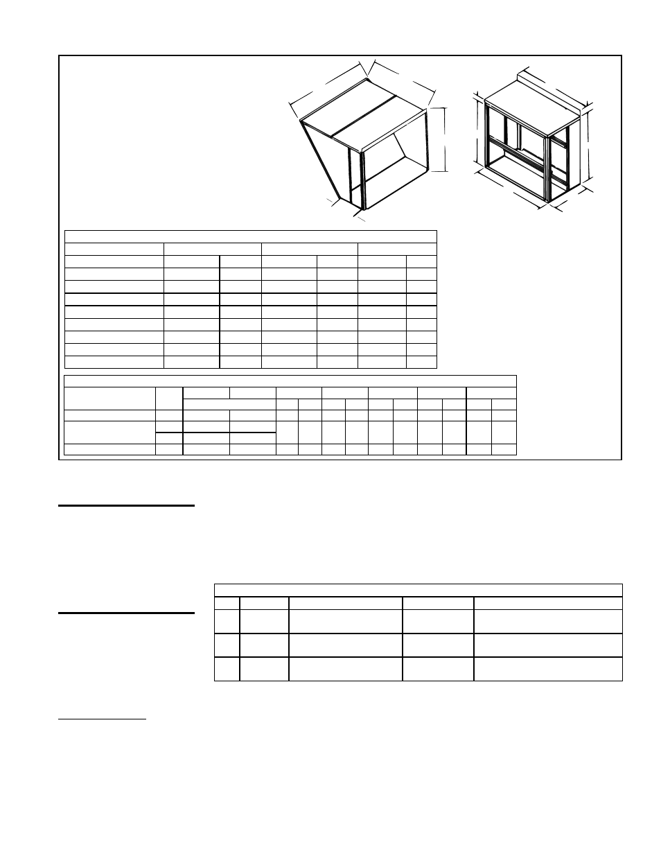
FIGURE 9 -
Dimensions
and Weights
Dimensions
Size
1-20, 1-40, 1-50, 1-65
2-80, 2-120
3-180, 3-260
inches
mm
inches
mm
inches
mm
A
38
965
62
1575
74-1/4
1886
B
55
1397
54
1372
64
1626
C
36
914
47-1/2
1207
61-3/8
1559
D
35-9/16
903
59-9/16
1513
71-9/16 1818
E
33-1/8
841
44-5/8
1133
58-1/2
1486
F
19-1/2
495
19-1/2
495
19-1/2
495
G (Duct Connection)
32-15/16
837
56-15/16
1446
69-3/8
1762
H (Duct Connection)
30-3/8
772
41-7/8
1064
57-7/16 1459
Weights and Filter Sizes
Model Sizes
Fltr
Qty
AS6, AW3 AS7, AW6
AS2
AS6
AS7
AW3
AW6
Filter Size
lbs
kg
lbs
kg
lbs
kg
lbs
kg
lbs
kg
1-20, 1-40, 1-50, 1-65
3
12x35x1
12x35x2 225 102 250 113 270 122 100
45
120
54
2-80, 2-120
4
12x35x1
12x35x2 310 141 350 159 380 172 150 68 180 82
4
12x24x1
12x24x2
3-180, 3-260
12
12x35x1
12x35x2 400 181 450 204 490 222 200
91
240 109
Installation Instructions for Optional Screened Air Hood for Outdoor Units (Options AS2,
AS6, AS7) and Filter Sections for Indoor Units (Options AW3, AW6)
All of these air inlet accessories are designed to be attached directly to the system
cabinet. To prevent damage, it is recommended that the system be set in its permanent
location before installing the air hood or filter cabinet option. All are shipped separately;
installation requirements depend on the size (see below).
Provide a minimum of 14" (356mm) clearance from the bottom of the air hood to the
mounting surface.
Hood and Filter Cabinet Options by ITEM and Application
Item
Options Description
For Sizes
Installation Requirements
1
AS2, AS6,
AS7
Outdoor Screened Air Hood
with & without filters
1-20, 1-40, 1-50,
1-65, 2-80, 2-120
Factory Assembled; Field Installed -
Follow instructions below.
2
AS2, AS6,
AS7
Outdoor Screened Air Hood
with & without filters
3-180, 3-260
Field Assembled and Installed - Follow
instructions pages 12 to 15.
3
AW3, AW6 Indoor Filter Cabinet with
Filters
All
Factory Assembled; Field Installed -
Follow instructions below.
CAUTION: It is
recommended
that the inlet to the
outside air hood
NOT be facing into
prevailing wind.
Installation STEPS for
ITEMS 1 and 3 in the
Table above - Refer to
FIGURE 10.
1) Remove the sheetmetal screws from the bottom rear inset and across the top rear
of the cabinet.
2) Align edges of assembly to the slip grooves. Slide top edge of assembly under the
lip formed by the top rear of the cabinet.
3) Rotate the inlet assembly so that it fits into the recess across the bottom of the
cabinet. Replace all screws removed in Step 1.
4) If the system has filters with an optional dirty filter light, follow the instructions
beginning on page 18 to attach the sensing tubes.