0 dimensions and clearances, 1 dimensions, 2 clearances – Reznor EEDU Unit Installation Manual User Manual
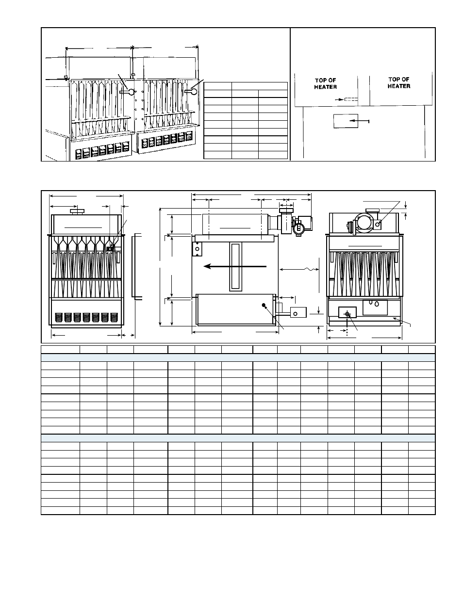
Page 7: Figure 4c - front view of coupled furnaces, Figure 4d - top view of coupled furnaces, Figure 5 - model eedu dimensions - inches (mm)
Form I-EEDU, P/N 150492 R6, Page 7
FIGURE 4C - Front View of Coupled Furnaces
A
A + 2"
(51mm)
Limit
Control
Limit
Control
Size
"A"
75-100
14-5/8"
371mm
125-140 17-3/8"
441mm
170
20-1/8"
512mm
200
22-7/8"
581mm
225
25-5/8"
651mm
250
28-3/8"
721mm
300
33-7/8"
860mm
350
39-3/8" 1000mm
400
44-7/8" 1140mm
FIGURE 4D - Top View of Coupled
Furnaces
(NOTE: Access panel may be in top or
bottom of ductwork.)
Access panel for
limit control service
and observation of
coupled units.
Limit Control
(Discharge Duct)
4.0 Dimensions and Clearances
D
M
3-1/2 (89)
Limit Control
J (Duct Width)
4(102) Minimum Unit S
pacing
Combustion Air Openings
of Hangers
16 (406)
5 (127)
K
L
C
6-3/4
(171)
18 (457)
Duct
Height
8-1/8
(206)
3/4
(19)
AIR
FLOW
26
660mm
3-1/2
(89)
4-1/4
(108)
29 (737)
KEEP CLEAR
FOR SERVICE
B
Combustion
Air Opening
H
Electric Supply
REAR VIEW
SIDE VIEW
FRONT VIEW
A
CL
F
E
G (Gas Connection)
View port
(both sides)
C of Hangers
L
3/4
(19)
FIGURE 5 - Model EEDU Dimensions - inches (mm)
4.1 Dimensions
Size
A
B
C
D
E
F
G-Nat G-Pro
H
J
K
L
M
Dimensions- inches
75, 100
35
14-1/4
35-11/16
14-5/8
4-3/8
3-15/16
1/2
1/2
5/8
12-1/2
7-1/4
7-7/16
4-5/8
125, 140
35
17
35-11/16
17-3/8
4-3/8
3-15/16
1/2
1/2
5/8
15-1/4
7-1/4
7-7/16
6
170
35
19-3/4
35-11/16
20-1/8
4-3/8
3-15/16
1/2
1/2
5/8
18
7-1/4
7-7/16
7-3/8
200
35
22-1/2
35-11/16
22-7/8
4-3/8
3-15/16
1/2
1/2
5/8
20-3/4
7-1/4
7-7/16
8-3/4
225
35-3/4
25-1/4
35-11/16
25-5/8
4-3/8
4-15/16
1/2
1/2
1-3/8
23-1/2
7-1/4
7-7/16
10-1/8
250
35-3/4
28
35-11/16
28-3/8
7-1/8
4-15/16
1/2
1/2
1-3/8
26-1/4
7-1/4
7-7/16
11-1/2
300
36
33-1/2
38-1/8
33-7/8
9-7/8
5-15/16
3/4
1/2
1-3/8
31-3/4
9-9/16
7-5/8
13-7/8
350
36
39
38-1/8
39-3/8
12-5/8
5-15/16
3/4
1/2
1-3/8
37-1/4
9-9/16
7-5/8
16-5/8
400
36
44-1/2
38-1/8
44-7/8
15-3/8
5-15/16
3/4
1/2
1-3/8
42-3/4
9-9/16
7-5/8
19-3/8
Dimensions - mm
75, 100
889
362
906
371
111
100
13
13
16
318
184
189
117
125, 140
889
432
906
441
111
100
13
13
16
387
184
189
152
170
889
502
906
511
111
100
13
13
16
457
184
189
187
200
889
572
906
581
111
100
13
13
16
527
184
189
222
225
908
641
906
651
111
125
13
13
35
597
184
189
257
250
908
711
906
721
181
125
13
13
35
667
184
189
292
300
914
851
968
860
251
151
19
13
35
806
243
194
352
350
914
991
968
1000
321
151
19
13
35
946
243
194
422
400
914
1130
968
1140
391
151
19
13
35
1086
243
194
492
Unit must be installed so that clearances are provided for combustion air space, ser-
vice and inspection, and for proper spacing from combustible construction. Clearance
to combustibles is defined as the minimum distance from the heater to a surface or
object that is necessary to ensure that a surface temperature of 90°F above the sur-
rounding ambient temperature is not exceeded. See table on top of page 8.
4.2 Clearances
NOTE: See FIGURES 5
and 7 for illustrations of
service clearances.