0 maintenance and service (cont'd), 2 maintenance procedures (cont'd) – Reznor EEDU Unit Installation Manual User Manual
Page 28
Form I-EEDU, Page 28
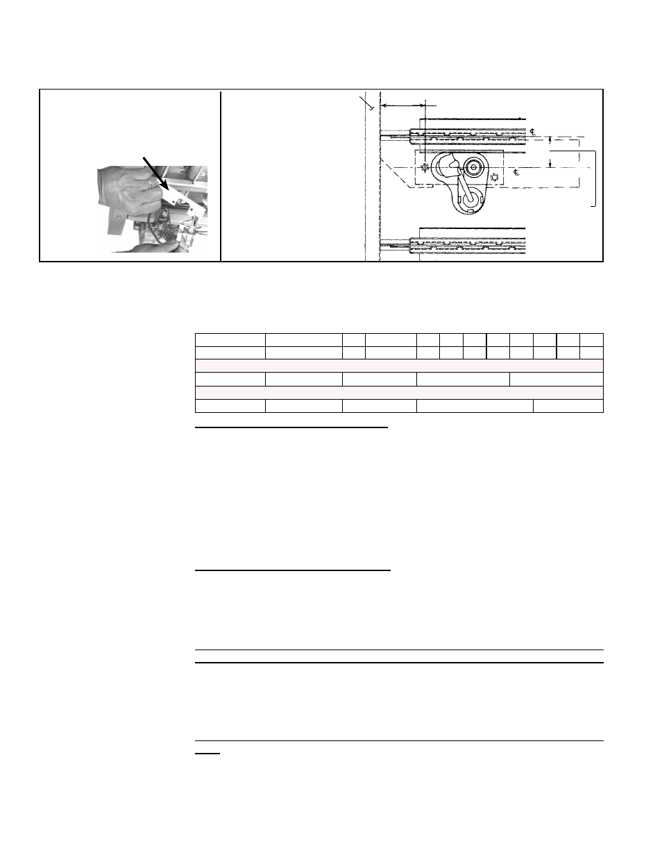
FIGURE 27A - Vertical Spark
Pilot
FIGURE 27B -
Pilot
Location
Burner
Rear
Support
2-3/4” (70mm)
of burner
of pilot
and sensor
3/4” (±1/32”)
19mm (±.8mm)
When re-installing the pilot,
be sure to include the pilot
hole cover plate.
Size
75
100
125
140 170 200 225 250 300 350 400
Qty
4
4
5
5
6
7
8
9
11
13
15
Burner Orifices for Sea Level Operation - Natural Gas
Drill Size (
P/N)
45 (
38678)
41 (
11792)
38 (
45870)
39 (
45871)
Burner Orifices for Sea Level Operation - Propane
Drill Size/ (
P/N)
1.2mm (
63003) 1.45mm (61652)
1.55mm (
61653)
53 (
9789)
Burner Orifices
Burners - Normally it is unnecessary to clean the main burners, but during the annual cleaning of the heat exchanger
tubes, it is wise to inspect the burners for plugged ports. Main burners may be cleaned using air pressure. Use an air
nozzle to blow out scale and dust accumulation from the burner ports. Alternately blow through the burner ports and the
venturi. Use a fine wire to dislodge any stubborn particles. Do not use anything that might change the port size.
Clean the burner rack flash carryover systems with air pressure.
10.2.3 Cleaning the
Heat Exchanger
Outer Surfaces (circulating air side) - To clean the outer surfaces of the heat
exchanger, gain access by removing the inspection panels in the ductwork or remove
the ductwork.
Remove the baffles between the heat exchanger tubes; see.
FIGURE 2B, page 5.
(
NOTE: If the heater has been converted to high CFM (see APPENDIX, page 30,
and Label on the unit), these baffles will have already been removed.) To remove the
baffles, remove the screws marked "A" in
FIGURE 2B, and slide each baffle forward.
Use a brush and/or an air hose to remove accumulated dust and grease deposits from
the heat exchanger tubes and the baffles. Re-install the baffles by sliding them into the
slot in the other end of the heat exchanger and replacing the screws. Secure ductwork
as necessary.
Inner Surfaces (combustion gas side) - The inner surfaces of the heat exchanger
can be reached for cleaning with the burner rack removed (See Paragraph 10.2.2.)
An air hose; a long (18 to 24-inch), 1/2" diameter stiff brush; a flashlight; and a mir-
ror are needed. The required procedure depends on the size of the furnace and the
date of manufacture. Follow these instructions to clean the inner surfaces of the heat
exchanger.
All Sizes 75, 100 and 125 (do not have heat exchanger "V" baffles) and Sizes
140-400 manufactured prior to 11/95 (do not have heat exchanger "V" baffles)
-- Remove the burner rack assembly. Use a furnace brush (or a piece of heavy wire
to which a piece of steel wool is attached). Brush up and down within the tubes until
all soot is removed. With an air hose or brush, clean the outside space between the
lower portions of the heat exchanger tubes to remove any accumulated dust or light
deposits.
Sizes 140 - 400 manufactured beginning 11/95 (have heat exchanger "V" baf-
fles) -- Remove the burner rack assembly. Make sure that the flue pipe is supported.
Remove the three screws that attach the venter housing to the outlet duct (pipe from
furnace to venter). The venter assembly will remain in place. Remove the six screws
used to attach the flue collection box to the top of the furnace. Remove the flue collec-
tion box exposing the heat exchanger tubes. The V-shaped tube baffles on the top of
the heat exchanger can now be removed.
10.2 Maintenance Procedures (cont'd)
10.0 Maintenance
and Service
(cont'd)
10.2.2 Burner Rack and Pilot (cont'd)