4 gas controls, 0 controls (cont'd), 3 fan control (cont'd) – Reznor EEDU Unit Installation Manual User Manual
Page 22: Warning
Form I-EEDU, Page 22
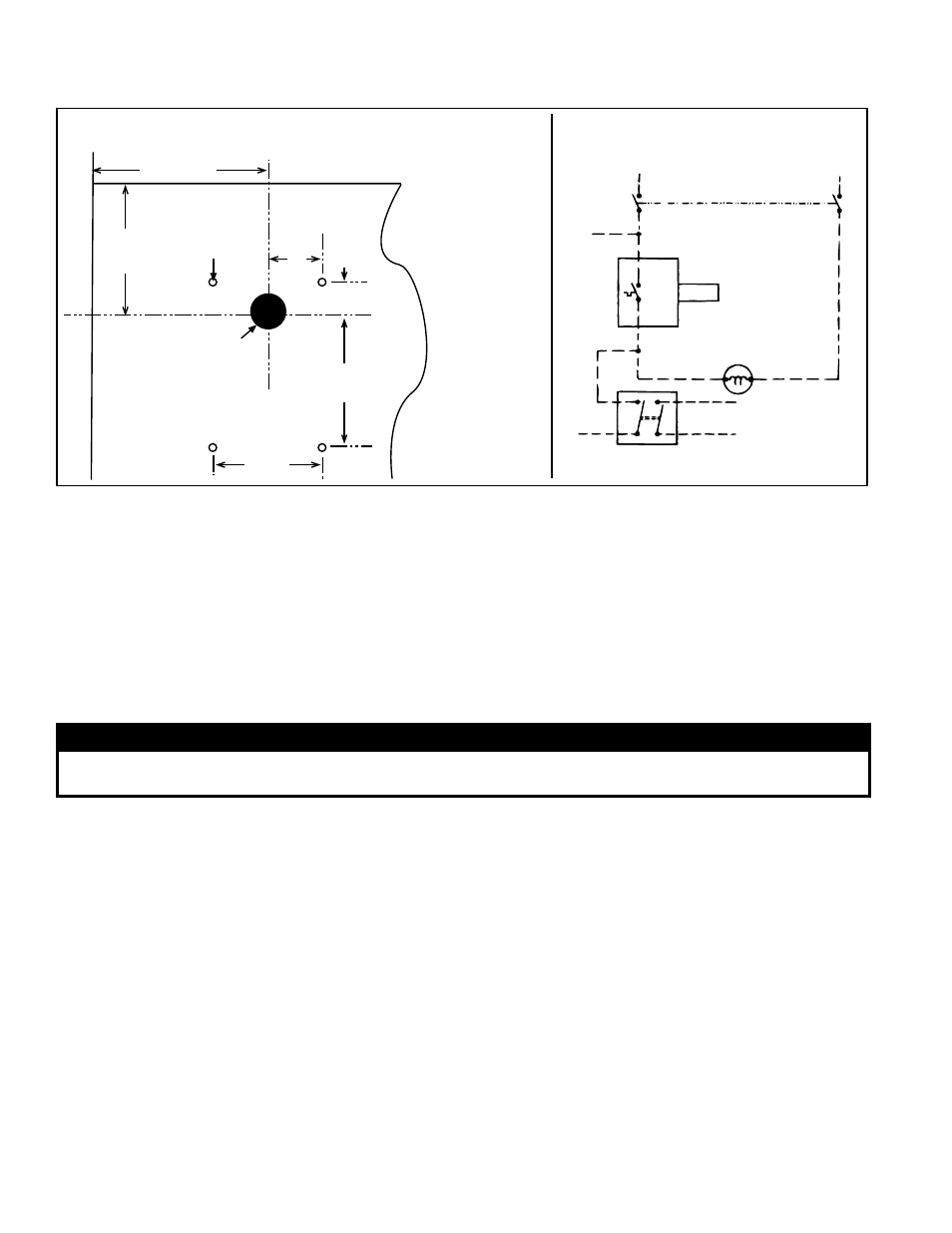
4 (102mm)
3
(76mm)
2-3/8
(60mm)
3
(76mm)
3/4 (19mm)
1-3/16 (30mm)
Drill one 13/16
(20.6mm) diameter
hole for the element.
Drill four 1/8
(3mm) diameter
holesfor screws.
(Discharge
Duct)
(Heater)
HOT
COM
120V or 230V
Power Supply
Line Switch
Fan
Line
Fan
Load
Blower Motor or Starter Coil
DP-ST Control Switch (Used with
Options AG3, AG8, AG9, and AG15)
To Gas Control
Circuit
Rating
120V - 14 - F.L.
120V - 84 - L.R.
230V - 7 - F.L.
230V - 42 - L.R.
FIGURE 20C - Typical Fan Control
Wiring (W.D. 145977)
Install the gasket
supplied in the
option kit between
the fan control and
the duct.
FIGURE 20B - Location of Fan Control Mounting Holes
8.4 Gas Controls
8.4.1 Gas Valve
All furnaces are equipped with a 24-volt combination valve which includes the auto-
matic electric on-off valve controlled by the room thermostat, the pressure regulator,
and the manual shutoff valve. The standard gas valve allows for single-stage control
from a single-stage, 24-volt thermostat.
WARNING
The operating valve is the prime safety shutoff. All gas supply lines must be free of dirt or scale
before connecting the unit to ensure positive closure. See Hazard Levels, page 2.
8.4.2 Optional Two-
Stage Operation -
Heating Only
NOTE: Not available on
Size 75 using propane.
8.4.3 Optional Two-
Stage Operation -
Makeup Air
The standard combination control valve is replaced with a two-stage combination gas
control valve providing for low fire or high fire operation controlled by a two-stage
thermostat. First stage (low fire) is factory set (not field adjustable). Both high and low
stages are controlled by a Servo regulator, maintaining constant gas input under wide
variations in gas supply pressure. See instructions in the envelope with the unit for
specific gas valve specifications, wiring, and operating instructions.
3. To be sure that the fan can continue to operate, the power supply to the heater
MUST NOT be interrupted except when servicing the heater.
4. If the customer wants the heater off at night, the gas valve circuit SHOULD BE
OPENED by a single pole switch wired in series with the thermostat. Some ther-
mostats are provided with this feature. Multiple units controlled from a single ther-
mostat are shut off in the same manner. For proper operation, be sure fan control
wiring is observed. See
FIGURES 20 A, B, & C for installation and wiring.
Two-stage makeup air units are equipped with a two-stage gas valve, but instead of
control from a two-stage room thermostat, the outlet air temperature is monitored and
controlled by a two-stage ductstat. When the discharge air temperature drops to the
setpoint, low fire is energized. If low fire cannot satisfy the ductstat setting, high fire is
energized.
Makeup air applications are usually adjusted to discharge an outlet air temperature
between 65°F and 75°F. In all applications, the allowable temperature rise of the fur-
nace in the installation dictates the limits of the ductstat temperature setting.
Depending on the option selection, the factory-installed sensor is either field-con-
nected by capillary tubing to the unit-mounted ductstat (Option AG3,
FIGURES 21),
or electrically connected to a remote electronic remote temperature selector (Option
AG15,
FIGURE 22).
NOTES: Makeup air option
requires field installed fan
control, see Paragraph 8.3.
This option is not available
on Size 75 using propane
gas.
8.0 Controls (cont'd)
8.3 Fan Control (cont'd)