0 mechanical (cont'd), 2 venting (cont'd) – Reznor EEDU Unit Installation Manual User Manual
Page 12
Form I-EEDU, Page 12
6.0 Mechanical
(cont'd)
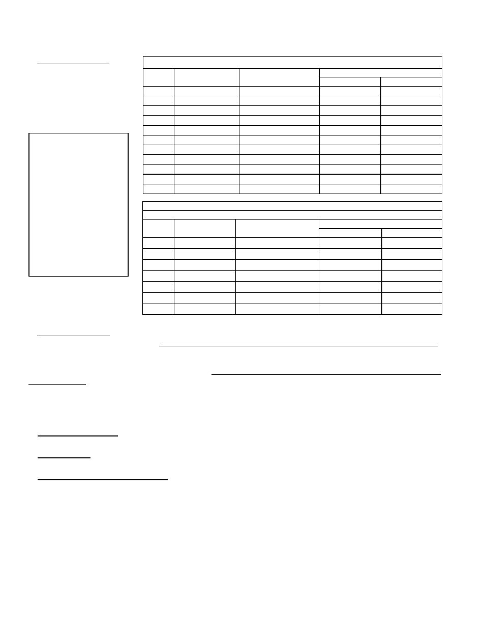
NOTE 1: If the system
contains all vertical pipe
or a combination of
vertical and horizontal
vent pipe, the Maximum
Permissible Vent Length
shown in TABLES 1
and 2 may be increased
one foot for each foot
of vertical pipe, up to a
maximum increase of 10
feet for Model Sizes 75 -
125 and up to 20 feet for
Model Sizes 140 - 400.
TABLE 1: Maximum Permissible Vent Lengths with Standard Vent Pipe Diameters
Size
Vent Pipe Diameter
(inches)
Maximum Vent Length
(see NOTE 1 left)
Equivalent Straight Length* - ft (M)
90°Elbow
45°Elbow
75
4
40 ft (12.2 M)
6 (1.8)
3 (.9)
100
4
50 ft (15.2 M)
7 (2.1)
3.5 (1.1)
125
4
50 ft (15.2 M)
7 (2.1)
3.5 (1.1)
140
4
50 ft (15.2 M)
7 (2.1)
3.5 (1.1)
170
4
50 ft (15.2 M)
7 (2.1)
3.5 (1.1)
200
4
50 ft (15.2 M)
7 (2.1)
3.5 (1.1)
225
5
50 ft (15.2 M)
9 (2.7)
4.5 (1.4)
250
5
50 ft (15.2 M)
9 (2.7)
4.5 (1.4)
300
6
50 ft (15.2 M)
11 (3.4)
5.5 (1.7)
350
6
50 ft (15.2 M)
11 (3.4)
5.5 (1.7)
400
6
50 ft (15.2 M)
11 (3.4)
5.5 (1.7)
TABLE 2: Optional Maximum Permissible Vent Lengths
(Requires an increase in vent pipe diameter.)
Size
Vent Pipe
Diameter (inches)
Maximum Vent Length
(see NOTE 1 left)
Equivalent Straight Length* - ft (M)
90°Elbow
45°Elbow
170
5
60 ft (18.3 M)
9 (2.7)
4.5 (1.4)
200
5
70 ft (21.3 M)
9 (2.7)
4.5 (1.4)
225
6
70 ft (21.3 M)
11 (3.4)
5.5 (1.7)
250
6
70 ft (21.3 M)
12 (3.7)
6 (1.8)
300
7
70 ft (21.3 M)
13 (4.0)
6.5 (2.0)
350
7
80 ft (24.3 M)
13 (4.0)
6.5 (2.0)
400
7
90 ft (27.4 M)
14 (4.3)
7 (2.1)
* Tables 1&2 - Reduce the
maximum vent length by the
amount indicated for each
elbow used.
4. Vent System Joints - Vent system joints depend on the installation and the type of pipe being used.
If installed as a Category III heater (required if more than half of the equivalent length of the vent system is horizontal)
and single-wall vent pipe is being used, use at least two non-corrosive screws per vent pipe joint and seal all joints
to prevent leakage of flue gases into the building. For sealing joints, tape suitable for 550°F is recommended (required
in California).
If installed as a Category III heater (required if more than half of the equivalent length of the vent sys-
tem is horizontal)
and vent pipe specifically approved for Category III vent systems is being used, follow the pipe
manufacturer's instructions for proper sealing.
If installed with a Category I vent system (allowed only if at least half of the equivalent length of the vent sys-
tem is vertical), use at least two non-corrosive screws per vent pipe joint on single-wall pipe or follow the pipe manu-
facturer's instructions for joining double-wall pipe. Refer to
FIGURE 10A when attaching vent cap to double-wall pipe.
5. Vent System Support - Support lateral runs every six feet (1.8M), using a non-combustible material such as strap
steel or chain. Do not rely on the heater for support of either horizontal or vertical vent pipe.
6. Condensation - Single-wall vent pipe exposed to cold air or run through unheated areas must be insulated. Where
extreme conditions are anticipated, install a means of condensate disposal.
7. Vent Terminal (Pipe and Vent Cap) - Terminate the vent system with a Reznor Option CC1 vent cap that in most
cases is the same size as the vent run. Heaters to be installed in the United States that are ordered with an optional
vent cap and all heaters ordered for Canada have a vent cap packaged with the heater. If the "standard" size vent pipe
listed in Vent Length Table 1 is used; install the vent cap provided.
If a vent cap is not included or if a non-standard size (Vent Length Table 2) of vent pipe is used, provide a Reznor
Option CC1 vent cap in the appropriate size.
NOTE: If the vent run is 7" vent pipe, install an 8" vent cap using a tapered
enlarger.
See the illustrations in
FIGURES 11A and 11B for requirements of either vertical or horizontal vent termination. The vent
terminal section may be either single-wall or double-wall (Type B) vent pipe.
If double-wall pipe is used in the vent terminal, follow the instructions in
FIGURE 10A to attach the vent cap and in FIG-
URE 10B to connect the double-wall pipe to the single-wall or Category III vent pipe run.
6.2 Venting (cont'd)
Specific Venting Requirements (cont'd)
3. Vent Length Tables