5 pilot and ignition systems, 6 burner carryover system and air adjustment, 0 controls (cont'd) – Reznor EEDU Unit Installation Manual User Manual
Page 24
Form I-EEDU, Page 24
8.5 Pilot and Ignition Systems
A gas-fired intermittent pilot is standard. The vertical pilot is located under the aeration
panel on the control end of the burner tray and is accessible only after the burner rack
has been removed. Remove the pilot for maintenance or service, such as checking the
wiring and cleaning. (See Paragraph 10.2.2) Pilot is target type with lint-free feature.
Pilot gas pressure should be the same as supply line pressure. (See Paragraph 6.1) If
required, adjust the pilot flame length to approximately 1-1/4" with the pilot adjustment
screw in the control valve body.
Intermittent Spark Ignition Safety Pilot Systems -- There are two types of intermit-
tent spark pilots -- one type shuts off the pilot gas flow between the cycles and the
other not only shuts off the pilot gas flow between cycles but also has a lockout device
that stops the gas flow to the pilot if the pilot fails to light in 120 seconds. The lockout
feature has a 1-hour retry or requires manual reset by interruption of the control circuit.
Propane units require the spark ignition with lockout.
Ignition Controller -- As part of the intermittent safety pilot systems, the ignition con-
troller provides the high voltage spark to ignite the pilot gas and also acts as the flame
safety device. After ignition of the pilot gas, the ignition controller electronically senses
the pilot flame. A low voltage DC electrical signal is imposed on the separate metal
probe in the pilot assembly. The metal probe is electrically insulated from ground. The
pilot flame acts as a conduction path to ground completing the DC circuit and proving
pilot flame. With pilot flame proven, the ignition controller energizes the main gas valve.
Service NOTE: If replacing
an earlier model of ignition
controller, order replace-
ment kit
P/N 257472 for
a unit with recycling gas
control Option AH2 or
P/N
257473 for Option AH3 gas
control with lockout. (Option
codes are listed on the unit
wiring diagram.)
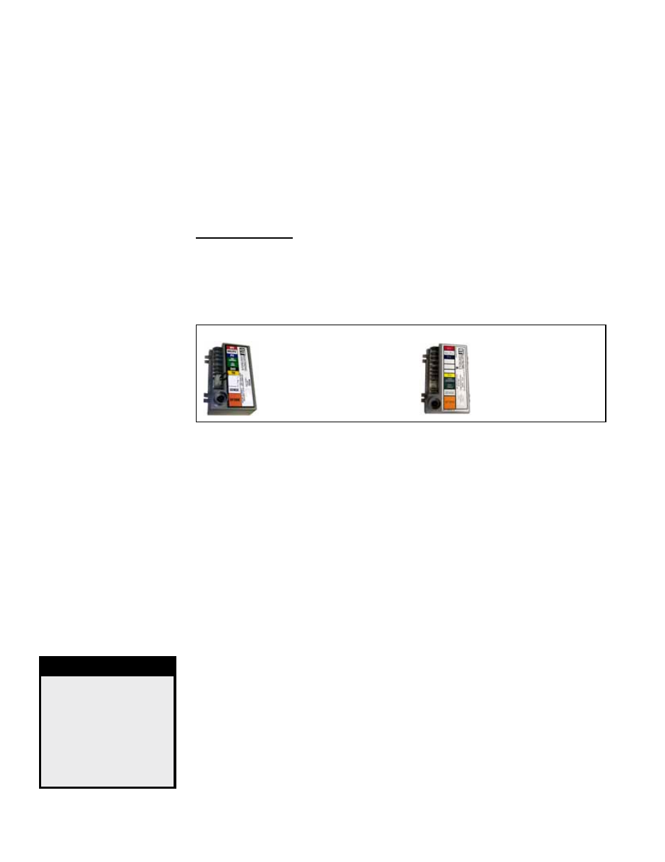
Recycling Ignition
Controller, UTEC
1003-638A, P/N
257009, for Option
AH2 Gas Control
Ignition Controller with
Lockout, UTEC 1003-
514, P/N 257010, for
Option AH3
Gas Control
FIGURE 24 - Ignition Controllers
8.0 Controls
(cont'd)
8.6 Burner
Carryover
System and Air
Adjustment
If no spark, check the following:
a) Voltage between Terminals TH and 7 should be at least 20 volts and no higher
than 32 volts. Refer to troubleshooting (Paragraph 10.3) if no voltage is observed.
b) Short to ground in the high tension lead and/or ceramic insulator.
c) Pilot spark gap should be approximately 7/64".
If the above conditions are normal and no spark occurs, replace the ignition controller
(See
Service NOTE on the left above).
NOTE: When checking for
spark with the pilot burner
removed from the burner
rack, the pilot assembly
must be grounded to the
heater for proper spark.
8.6.1 Burner Carryover
These duct furnaces have individually formed steel burners with accurately die-formed
ports to give controlled flame stability without lifting or flashback with either natural or
propane gas. The burners are lightweight and factory mounted in an assembly which
permits them to be removed as a unit for inspection or service.
All burners are equipped with two flash carryover systems that receive a supply of gas
simultaneously with the main burner. During regular service, check the main burner
ports, the carryover assemblies, and the orifices for cleanliness.
8.6.2 Burner Air Adjustment
Burner air shutters are not normally required on natural gas furnaces. Air shutters are
supplied on propane gas units and may require adjustment.
Before making any adjustments to the air shutters, allow the heater to operate for
about fifteen minutes with the air shutters open. The slotted screw on the end mani-
fold bracket moves the air shutters and adjusts all burners simultaneously. Turning
the screw clockwise opens the shutters; counterclockwise closes the shutters. After
the furnace has been in operation for 15 minutes, close the air shutters observing
the flame for yellow-tipping. Open the shutters until the yellow disappears. A limited
amount of yellow-tipping is permissible for propane gas. Other fuels should not display
any yellow-tipping.
When making the adjustment, close the air shutters no more than is necessary to elimi-
nate the problem condition.
DANGER
Failure to install
and/or adjust air
shutters according
to directions could
cause property
damage, personal
injury, and or death.