3 constructing bypass duct, Figure 13 - bypass duct – Reznor EEDU Unit Installation Manual User Manual
Page 15
Form I-EEDU, P/N 150492 R6, Page 15
6.3.3 Constructing
Bypass Duct
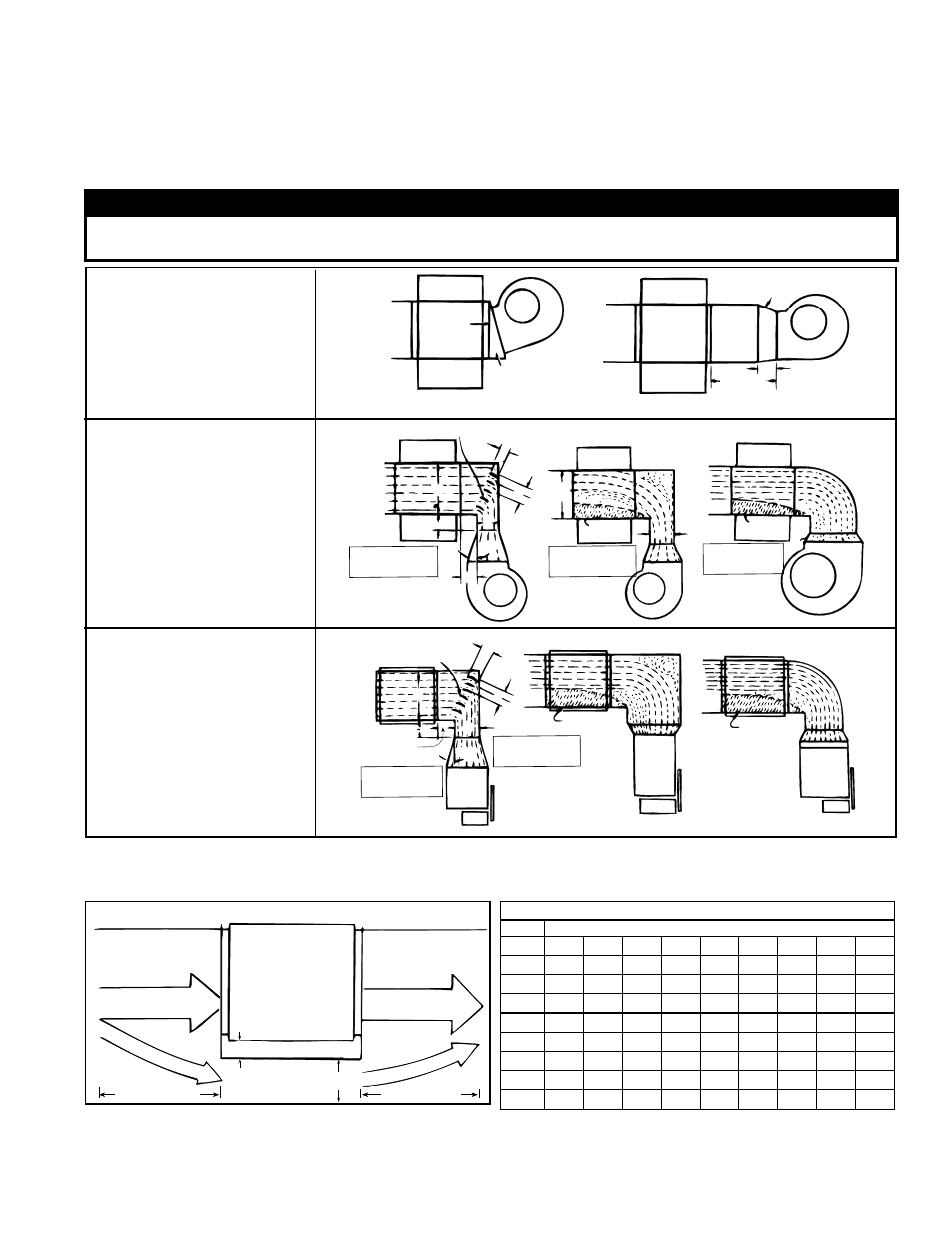
Top View
of Furnace
Control Side
Bypass Duct A
2 (51mm) minimum
18 (457mm)
18 (457mm)
FIGURE 13 - Bypass Duct
Bypass CFM
"A"
Pressure Drop through the Furnace
Width 0.10 0.15 0.20 0.25 0.30 0.35 0.40 0.45 0.50
3"
490
530
610
700
780
830
900
960 1010
4"
630
750
870
980 1090 1160 1250 1310 1400
5"
850 1010 1190 1300 1410 1520 1640 1730 1810
6"
1050 1290 1480 1650 1800 1940 2090 2200 2320
7"
1250 1510 1760 1960 2180 2320 2500 2650 2800
8"
1490 1810 2100 2350 2560 2760 2940 3110 3290
9"
1700 2100 2400 2700 2970 3200 3400 3600 3800
10"
1920 2350 2760 3090 3650 4020 4300 4550 4800
When the CFM of air throughput is greater than desirable or permissible for the unit,
a bypass duct may be constructed. Follow these instructions to determine the correct
size of the bypass duct.
Directions for Sizing
Bypass Duct
6.3.2 Duct Furnace
Blower Connections
Proper arrangements of blower and duct furnace with respect to angle of approach
of the duct connection and the arrangement of the discharge opening of the blower
are shown. Blowers should be bottom horizontal discharge when coupled to the duct
furnace. When a top horizontal discharge blower is connected to the duct furnace, be
sure that sufficient length of duct is provided to permit even flow of air at the end of the
duct. Or, baffles may be inserted between the blower and the heater to assure an even
flow of air across the heat exchanger. See illustrations in
FIGURE 12 A, B, and C.
FIGURE 12A - Straight
through Air Blower
Connection
Direct
Coupling
Slanted Transition
Suggested blower connections for straight through airflow.
Use either method for good air coverage and efficient operation.
15°
6 (152mm)
Remote
24
(610mm)
minimum
Turning Vanes
3(76mm)
3(76mm)
3(76mm)
6 (152mm)
6
(152mm)
X
15°
Y
No air
X
No air
Z
NOTE: X should
never be less than
1/2 Y
NOTE: X should
never be less
than 1/2 Y
NOTE: Angle Z
should never be
more than 15°
Turning Vanes
3(76mm)
3(76mm)
3(76mm)
6 (152mm)
6 (152mm)
Z
NOTE: Angle Z
should never be
more than 15°
X
15°
No air
GOOD
GOOD
POOR
POOR
POOR
No air
POOR
Y
Y
NOTE: X should
never be less
than 1/2 Y
WARNING
The furnace must be installed on the positive pressure side of the air-circulating blower. See Hazard
Levels, page 2.
FIGURE 12B - Blower
Connection With
Elbows Up or Down
FIGURE 12C - Blower
Connection with Elbows
Right or Left
1) From the tables in Paragraph 6.3.1, find the pressure drop (P.D.) and the allowable
CFM for the furnace that is being installed.
Example: Standard Size 170 @ 70°F temperature rise; P.D. .33; CFM 1790