0 mechanical (cont'd), 3 duct furnace airflow (cont'd) – Reznor EEDU Unit Installation Manual User Manual
Page 16
Form I-EEDU, Page 16
6.0 Mechanical
(cont'd)
G
3/4
(19)
3/4 (19)
18
(457)
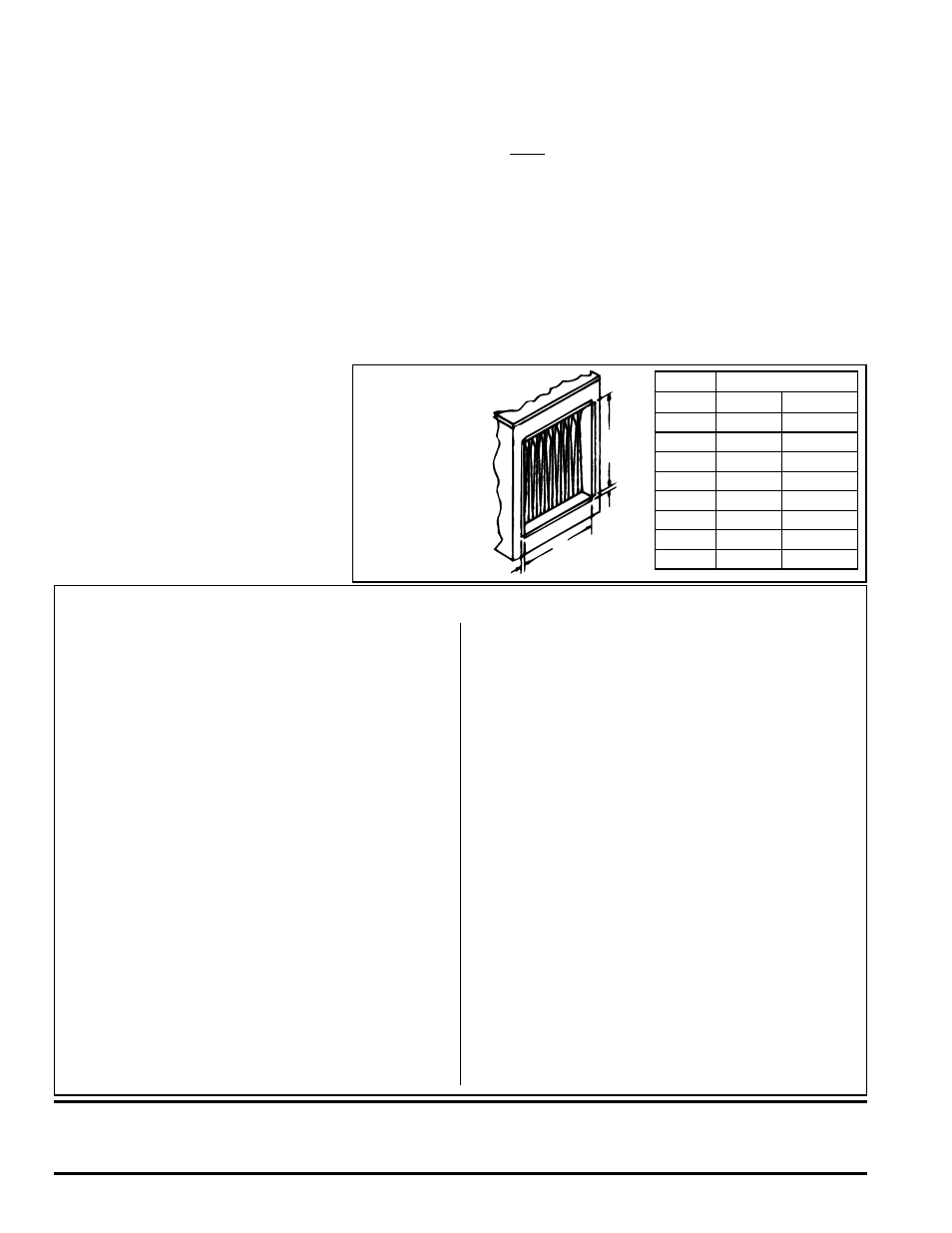
FIGURE 14 -
Duct
Connection
Dimensions -
inches (mm)
NOTE: If the furnace is equipped with a
unit-mounted ductstat (Option AG3), the
sensing bulb must be removed from the
mounting bracket (save the retainer clip)
before the ductwork can be attached.
See instructions in Paragraph 8.4.3 for
re-mounting the sensor.
Size
G
75, 100 12-1/2"
318mm
125, 140 15-1/4"
387mm
170
18"
457mm
200
20-3/4"
527mm
225
23-1/2"
597mm
250
26-1/4"
641mm
300
31-3/4"
806mm
350
37-1/4"
946mm
400
42-3/4"
1086mm
6.3.4 Duct Connections
6.3 Duct Furnace
Airflow (cont'd)
• Type of Ductwork - The type of duct installation to
be used depends in part on the type of construction
of the roof (whether wood joist, steelbar joist, steel
truss, pre-cast concrete) and the ceiling (whether
hung, flush, etc.).
• Ductwork Material - Rectangular duct should be
constructed of not lighter than No. 26 U.S. gauge
galvanized iron or No. 24 B & S gauge aluminum.
• Ductwork Structure - All duct sections 24 inches
(610mm) or wider, and over 48 inches (1219mm) in
length, should be cross broken on top and bottom
and should have standing seams or angle-iron
braces. Joints should be S and drive strip, or locked.
• Through Masonry Walls - No warm air duct should
come in contact with masonry walls. Insulate around
all air duct through masonry walls with not less than
1/2" (1" is recommended) of insulation.
• Through Unheated Space - Insulate all exposed
warm air ducts passing through an unheated space
with at least 1/2" (1" is recommended) of insulation.
• Duct Supports - Suspend all ducts securely from
adjacent buildings members. Do not support ducts
from unit duct connections.
• Duct Sizing - Proper sizing of the supply air
ductwork is necessary to ensure a satisfactory
heating installation. The recognized authority for
such information is the Air Conditioning Contractors
Association, 2800 Shirlington Road, Suite 300,
Arlington, VA 22206 (www.acca.org). A manual
covering duct sizing in detail may be purchased
directly from them.
• Removable Panels - The ducts should have
removable access panels on both upstream and
downstream sides of the furnace. These openings
must be accessible when the furnace is in service
and should be a minimum of 6" x 10" in size so
smoke or reflected light may be observed inside the
casing to indicate the presence of leaks in the heat
exchanger. The covers for the openings must be
attached in such a manner as to prevent leakage.
See
FIGURE 15A.
• Supply Air Duct/Furnace Horizontal Connection
- The seal between the furnace and the duct must
be mechanical. Duct connection should be made
with "U" type flanges on the top and bottom of the
connecting duct. Slide the duct over the flanges of the
heater giving an airtight fit. Provide "U" type channels
for the other side flanges to ensure tight joints. Use
sheetmetal screws to fasten ducts and "U" channels
to the furnace flange. See
FIGURES 15B and 15C.
CAUTION: Joints where ducts attach to furnace must be sealed securely to prevent air leakage into
burner rack area. Leakage can cause poor combustion, pilot problems, shorten heat exchanger life
and cause poor performance. See Hazard Levels, page 2.
2) Subtract the allowable CFM from the actual CFM of the installation to determine
how much air must be diverted through the bypass duct.
Example: Blower CFM 3000
Allowable CFM -1790
Bypass CFM 1210
3) Go to the column in the Bypass CFM Chart that is closest to the pressure drop
through the heater. Move down in that column until you find the larger CFM
closest to the answer in Step 2).
Example: Go to P.D. Column .35; move down to Bypass CFM 1520
4) Move to the left column to find out the required size of the bypass duct.
Example: Bypass Duct Size is 5"
Locate the bypass duct on the side of the furnace opposite the controls and 2" from the
heat exchanger side panel. Extend the bypass duct 18" (457mm) beyond the furnace
on both the inlet and outlet ends.
NOTE: Not all capacities
are covered in the
bypass duct chart. If your
installation is not covered,
consult your Reznor
representative or the factory
to determine the appropriate
size of the bypass duct.
Directions for Sizing Bypass Duct (cont'd)
Requirements and Suggestions for Connecting and Installing Ducts