Reznor EEDU Unit Installation Manual User Manual
Page 23
Form I-EEDU, P/N 150492 R6, Page 23
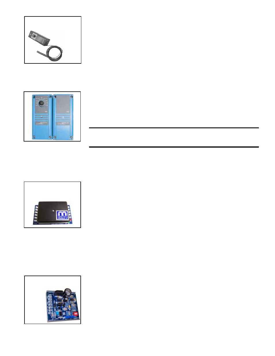
FIGURE 22 - (A) Remote
Temperature Selector
and (B) Stage-Adder
Module - Option AG15
(A)
(B)
8.4.4 Optional
Electronic Modulation
FIGURE 23B - Signal
Conditioner in Option
AG21
NOTE: Requires field-installed fan control (Option CQ1). See Paragraph 8.3.
The type and capability of the electronic modulation system, depends on the option
selected. Electronic modulation options are identified by a suffix to the Serial No.
printed on the heater rating plate. AG7 is identified as MV-1; AG8 is identified as MV-3;
AG9 is identified as MV-4; and AG21 is identified as MV-A.
Electronic Modulation between 50% and 100% Firing Rate (Options AG7, AG8,
AG9) - Depending on the heat requirements as established by the thermistor sensor,
the burner modulates between 100% and 50% firing. The thermistor is a resistor that
is temperature sensitive in that as the surrounding temperature changes, the Ohms
resistance changes through the thermistor. This change is monitored by the solid state
control center (amplifier) which furnishes varying DC current to the modulating valve to
adjust the gas input. The amplifier is shipped separately for field mounting.
Each modulating valve is basically a regulator with electrical means of raising and
lowering the discharge pressure. When no DC current is fed to this device, it functions
as a gas pressure regulator, supplying 3.5" w.c. pressure to the main operating valve.
Electronic modulation for heating controlled by a specially designed room thermo-
stat (60°-85°F) is identified as Option AG7. Electronic modulation control systems for
makeup air applications controlled by a duct sensor (See Paragraph 6.3.5.) and tem-
perature selector (55-90°F) are identified as either Option AG8 or Option AG9. The
temperature selector setting for Option AG8 is on the amplifier; Option AG9 has a
remote temperature selector. Both systems are available with an override thermostat.
Refer to the wiring diagram supplied with the furnace for proper wiring connections.
Computer Controlled Electronic Modulation between 50% and 100% Firing Rate
(Option AG21) - With this option the furnace is equipped with a Maxitrol signal condi-
tioner which operates much the same way as the amplifier above to control the regula-
tor valve. The conditioner accepts an input signal of either 4-20 milliamps or 0-10 volts
from a customer-supplied control device such as a computer. With the dip switches on
the conditioner in the "on" positions, the conditioner accepts a 4-20 milliamp signal. In
the "off" positions, the conditioner accepts a 0-10V signal. The conditioner converts the
signal to the 0 to 20 volt DC current required to control the modulating valve.
The conditioner, the conditioner relay, the transformer, a fuse box with cover, and hard-
ware are shipped separately for field installation. Follow the conditioner manufacturer's
instructions and the wiring diagram supplied with the unit.
FIGURE 23A -
Amplifier in Options
AG7, AG8, and AG9
FIGURE 21 - Ductstat
and Parts, Option AG3
Ductstat,
P/N 41700
Optional Ductstat with Capillary Tubing (Option AG3) - The ductstat is attached to
the furnace and is connected by a capillary tubing to the sensor. For shipping the sen-
sor is temporarily mounted on a bracket on the inner part of the furnace duct side (See
FIGURE 16A). See Paragraph 6.3.5 for instructions on re-locating the sensor bulb to
the discharge duct.
The dial has an adjustable range from 60° to 100°F with a fixed differential of 3°F. Due
to different CFM settings and outside air temperatures, the average downstream outlet
air temperature may not match the ductstat exactly. After the installation is complete,
adjust the ductstat to achieve the desired average outlet air temperature.
Optional Ductstat with Electronic Remote Setpoint Module (Option AG15) - The
remote modules in
FIGURE 22 and a required transformer are shipped separately
for field installation. (Do not wire the remote module to the control transformer on the
furnace.)
The sensor is shipped separately for installation in the discharge duct (See instructions
in Paragraph 6.3.5).
Follow the wiring diagram with the unit and the manufacturer's instructions for wiring
and installation.
There will be one module for selecting temperature and one-stage adder module as
illustrated in
FIGURE 22. The remote temperature selector has a temperature operat-
ing range to 130°F.
CAUTION: The remote temperature selector heat/cool selector switch
is factory-set in cool position. To function properly, set switch to heat
position.