3 duct furnace airflow, 0 mechanical (cont'd), 2 venting (cont'd) – Reznor EEDU Unit Installation Manual User Manual
Page 14: 1 pressure drop and temperature rise by size, Horizontal vent terminal (figure 11b) clearances
Form I-EEDU, Page 14
6.2 Venting (cont'd)
6.0 Mechanical
(cont'd)
Venting Requirements cont'd)
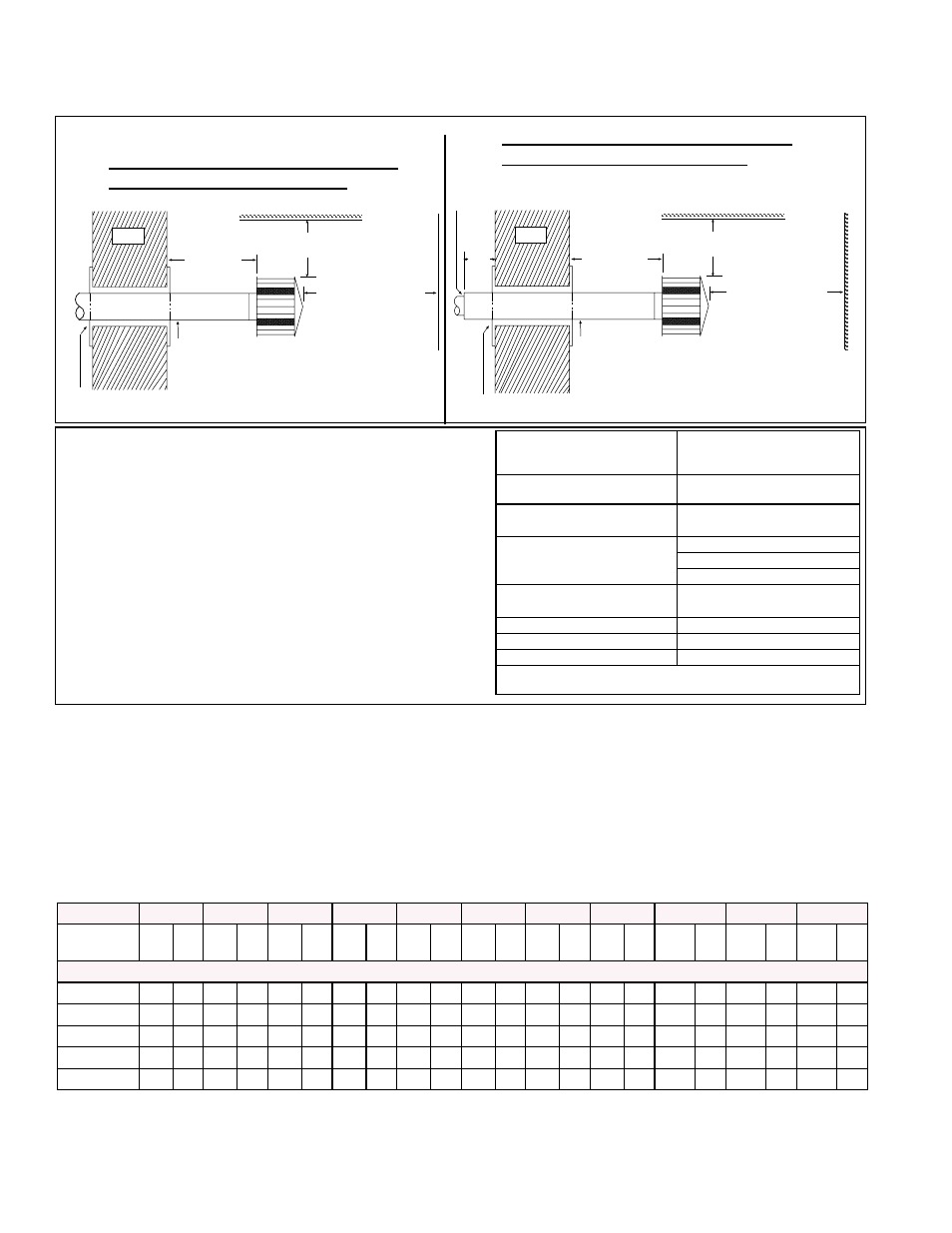
FIGURE 11B - Horizontal Vent Terminal
A clearance thimble is required when flue pipe extends through combustible
materials. Follow the instructions of the thimble or vent pipe manufacturer.
Pitch flue pipe down
toward outlet 1/4 per foot for
condensate drainage. (NOTE: Slope
applies to entire horizontal vent run.)
12
(305 mm)
minimum
Wall
Roof or Building Overhang
3 ft (1M)
minimum
6 ft (1.8M) minimum
Reznor Option CC1Vent
Cap - note positions of
vent cap openings
(shaded areas)
Parapet or
Adjoining Building
A clearance thimble is required when flue pipe extends through combustible
materials. Follow the requirements of the double-wall pipe manufacturer.
Pitch flue pipe down
toward outlet 1/4 per foot for
condensate drainage. (NOTE: Slope
applies to entire horizontal vent run.)
12
(305 mm)
minimum
Wall
Roof or Building Overhang
3 ft (1M)
minimum
6 ft (1.8M) minimum
Reznor Option CC1
Vent Cap - note positions
of vent cap openings
(shaded areas)
Parapet or
Adjoining Building
Double-Wall
Vent Pipe*
*Follow the instructions in FIGURE 10B to join the
double-wall vent terminal section to a single-
wall vent run and to seal the connection.
6 (152mm) minimum
Single-Wall or Category III Vent Run
and Single-Wall Terminal End
Single-Wall or Category III Vent Run
and Double-Wall Terminal End
6.3 Duct Furnace
Airflow
To determine temperature rise, the inlet and outlet air temperatures should be mea-
sured at points not affected by heat radiating from the heat exchanger. The Tempera-
ture Rise and Pressure Drop chart shows the approved temperature rise range with the
required CFM and the internal pressure drop for each size of unit.
The duct furnace must be installed on the positive pressure side of the field-supplied
blower. The air throughput must be within the CFM range stated on the heater rating
plate. The air distribution must be even over the entire heat exchanger. Turning vanes
should be employed in elbows or turns in the air inlet to ensure proper air distribution
(See Paragraph 6.3.2).
6.3.1 Pressure Drop and
Temperature Rise by
Size
Size
75
100
125
140
170
200
225
250
300
350
400
Temperature
Rise
CFM P.D. CFM P.D. CFM P.D. CFM P.D. CFM P.D. CFM P.D. CFM P.D. CFM P.D. CFM P.D. CFM P.D. CFM P.D.
Model EEDU (80% thermal efficient)
50°F
1105 0.24 1475 0.43 1840 0.49 2065 0.65 2505 0.67 2945 0.67 3315 0.69 3685 0.67 4420 0.70 5160 0.75 5895 0.77
60°F
920 0.16 1225 0.30 1535 0.33 1720 0.43 2085 0.46 2455 0.46 2765 0.47 3070 0.45 3685 0.47 4300 0.52 4915 0.52
70°F
790 0.10 1050 0.21 1315 0.25 1475 0.32 1790 0.33 2105 0.35 2370 0.36 2630 0.34 3160 0.35 3685 0.38 4210 0.38
80°F
695 0.07 920 0.16 1150 0.20 1290 0.24 1565 0.25 1840 0.26 2070 0.27 2300 0.26 2765 0.27 3225 0.28 3685 0.28
90°F
615 0.05 815 0.12 1020 0.17 1145 0.20 1390 0.19 1635 0.20 1840 0.21 2045 0.20 2455 0.22 2565 0.23 3275 0.22
If it is determined that the blower CFM is greater than allowed or desirable, see Para-
graph 6.3.3 for instructions on determining the correct size of bypass duct required or
see the
APPENDIX, page 30, for instructions on converting the furnace for a higher
CFM application.
Structure
Minimum Clearances for Vent
Termination Location (all
directions unless specified)
Forced air inlet within 10 ft
(3.1m)
3 ft (0.9m) above
Combustion air inlet of another
appliance
6 ft (1.8m)
Door, window or gravity air inlet
(any building opening)
4 ft (1.2m) horizontally
4 ft (1.2m) below
3 ft (0.9m) above
Electric meter, gas meter * and
relief equipment
4 ft (1.2m) horizontally
Gas regulator *
3 ft (0.9m)
Adjoining building or parapet
6 ft (1.8m)
Grade (ground level)
7 ft (2.1m) above
*Do not terminate the vent directly above a gas meter or service
regulator.
Horizontal Vent Terminal (FIGURE 11B) Clearances
The location of the termination of the horizontal vent system
must be in accordance with National Fuel Gas Code Z223.1.
See table for required minimum clearances.
If the vent terminal is to be installed near ground level, position
it at least six inches above maximum anticipated snow depth.
NOTE: Maintain the required clearance from the wall to
the vent terminal cap for stability under wind conditions
and to protect the building.
Products of combustion can cause discoloration of some build-
ing finishes and deterioration of masonry materials. Applying a
clear silicone sealant that is normally used to protect concrete
driveways can protect masonry materials. If discoloration is
an esthetic problem, relocate the vent or install a vertical vent.