Figure 15a - connecting ductwork to the furnace – Reznor EEDU Unit Installation Manual User Manual
Page 17
Form I-EEDU, P/N 150492 R6, Page 17
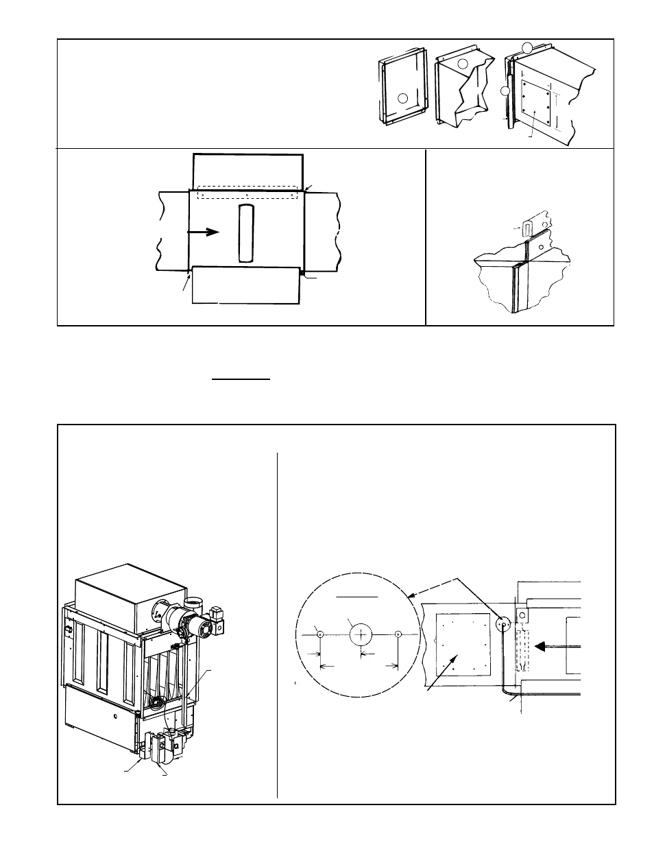
FIGURE 15A - Connecting Ductwork to the Furnace
1) Flanges on the heater turn out as shown.
2) Shape duct connection as shown -- "U" on top and bottom;
"L" on sides.
3) Slide "U" form over heater flange making connection.
4) Form "U" strips to seal ends. Drill and lock with sheetmetal
screws.
Heater
Duct
Access Panel in Duct
6
(152mm)
10 (254mm)
1
2
3
U
Channel
4
Furnace
U Channel of
Light Gauge Metal
Duct
Joints where ducts attach to
the furnace must be sealed
securely to prevent air leakage
which may disturb combustion.
Excessive leakage
here could have an
effect on combustion
causing premature damage to the heat exchanger and/or causing delayed ignition.
Air Flow
Direction
Warm air leakage here
would have an adverse
effect on combustion.
FIGURE 15C - The seals
between the furnace and the
duct must be mechanical. "U"
channel method as illustrated.
FIGURE 15B -
Attachment
of Duct to
Furnace
6.3.5 Discharge Air
Sensor for Makeup Air
Application
Option AG3 (two-stage makeup air) - The unit-mounted ductstat has a capillary tube
with a sensor bulb. The capillary and bulb must be moved out the way before install-
ing ductwork and then field-installed in the discharge duct. Refer to
FIGURE 16A and
follow the instructions.
All makeup air options (Options AG3, AG15, AG8, and AG9) require that the sensor be
field-installed in the discharge ductwork. Follow the instructions that apply.
Shipping
Angle -
Remove
before
attaching
ductwork.
Ductstat Bracket
- Option AG3
Ductstat -
Option AG3
Ductstat Capillary with
sensing bulb attached
inside the furnace. To
connect ductwork, remove
the bulb with the bracket.
(Save bracket and clip.)
FIGURE 16A - Installing Capillary Sensor Bulb in Discharge Ductwork (Option AG3)
The ductstat and the sensor are connected
by a permanently attached capillary tub-
ing. Before attaching ductwork, remove the
capillary tubing sensor bulb with the bracket
from its shipping position on the inside of
the furnace. After the ductwork is attached
to the furnace, follow the instructions on
the right to install the sensor bulb in the dis-
charge duct.
1/2” Diameter
1/8” Dia
3/4”
(19mm)
1-1/2” (38mm)
Capillary Tubing
to Ductstat
Airflow
Hole Pattern
Access
Panel
Instructions to Install Sensing Bulb in the Discharge Duct
Since the sensor is larger than the tubing, a gasket and gasket retainer
plate are needed to plug the hole and protect the capillary tubing
where it passes through the ductwork. These parts were shipped loose
with the furnace (See Paragraph 3.2). Two field-supplied sheetmetal
screws will be needed to attach the plate.
1) Drill the Holes - Refer to the illustration below and select a location on
the ductwork so that a minimum length of capillary tubing will be inside the
ductwork. Following the "hole pattern", drill holes in the ductwork.
Remove the ductwork access panel (
FIGURE 15A).
2) Install the Sensor - Remove the sensor bulb from the bracket. Push the
sensor through the 1/2" hole. Reaching through the access hole, use the
retaining clip to re-attach the sensor to the bracket.
3) Install the Gasket and Retainer Plate - Slide the gasket (cut a slit) and
hole retainer plate over the capillary tubing. With the gasket next to the
ductwork, attach the hole retaining plate with field-supplied sheetmetal
screws (as illustrated above). Close the ductwork access panel.