Reznor EEDU Unit Installation Manual User Manual
Page 27
Form I-EEDU, P/N 150492 R6, Page 27
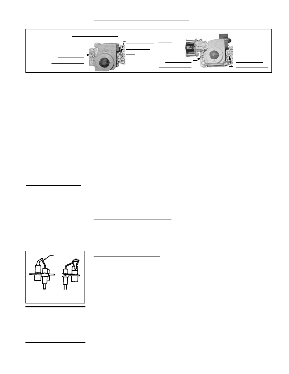
Single-Stage Valve
1/8" INLET
Pressure Tap
1/8” Outlet
Pressure
Tap
FIGURE 25 -
Gas Valve
Shutoff
Check
Instructions for Required Gas Valve Check:
1) Locate the 1/8” FPT INLET pressure tap on the combination valve (FIGURE 25).
1/8” Outlet
Pressure Tap
Two-Stage
Valve
1/8" INLET
Pressure Tap
1. Turn off the gas supply.
2. Turn off the electric supply.
3. Remove bottom rear panel (located on the manifold side of the furnace) by
removing the two screws from each side.
4. Mark and disconnect electric valve leads.
6. Uncouple the union in the gas supply.
7. Remove two sheetmetal screws in the bottom of the burner rack assembly.
8. Pull "drawer-type" burner rack out of the furnace.
To disassemble the burner rack:
1. Remove flash carryover system (screws located at rear of burner drawer).
2. Remove burner hold down clamp (located inside burner drawer under the pilot).
3. Pull main burners horizontally away from injection opening and lift out.
Follow the instructions below to clean. To re-assemble and replace, reverse the above
procedures being careful not to create any unsafe conditions.
Cleaning Pilot and Burners
Pilot - The pilot is located under the aeration panel on the control end of the burner tray
and is accessible only after the burner rack assembly has been removed. In the event
the pilot flame is short and/or yellow, check the pilot orifice for blockage caused by lint
or dust accumulation. Remove the pilot orifice and clean with air pressure. DO NOT
REAM THE ORIFICE. Check and clean the aeration slot in the pilot burner.
Clean the metal sensing probe and the pilot hood with an emery cloth and wipe off the
ceramic insulator. Check the spark gap; spark gap should be maintained to .100". After
the pilot is cleaned, blow any dirt away with compressed air. The combination valve
includes a pilot adjustment screw. To adjust, remove cap screw and adjust the pilot
flame to approximately 1-1/4".
Pilot System - No periodic maintenance of the ignition control box is required. How-
ever, each season the lead wires should be checked for insulation deterioration and
good connections. Proper operation of the electronic spark ignition system requires
a minimum flame signal of 0.2 microamps as measured by a microampmeter. Do not
attempt to disassemble the ignition controller. There are no field replaceable compo-
nents in the control enclosure.
CAUTION: Due to
high voltage on pilot
spark wire and pilot
electrode, do not
touch when energized.
10.2.2 Burner Rack and
Pilot
Burner Rack Removal
Instructions
.100 spark
gap
FIGURE 26 - Pilot
Burner Spark Gap
NOTE: Operational
pressure settings and
instructions for checking
pressure settings are in
Paragraph 6.1.
2) With the manual valve turned off to prevent flow to the gas valve, connect a
manometer to the 1/8” inlet pressure tap in the valve.
NOTE: A manometer (fluid-
filled gauge) with an inches water column scale is recommended.
3) With the field-installed manual valve remaining closed, observe the manometer
for two to three minutes for an indication of gas pressure. No pressure should be
indicated on the manometer.
If the manometer indicates a gas pressure, the field-installed manual gas valve
must be replaced or repaired before the combination gas valve can be checked.
4) If the manometer does not indicate gas pressure, slowly open the field-installed
manual gas valve. After the manometer's indicated gas pressure has reached
equilibrium, close the manual shutoff valve. Observe the gas pressure. There
should be no loss of gas pressure on the manometer. If the manometer indicates
a loss of pressure, replace the combination gas valve before placing the heater in
operation.