Haltech IQ3 Data Logger Dash User Manual
Page 81
IQ3 Data Logger Dash Installation Manual
81
Note: The V_Net Sample rate of each of the modules to be monitored should be equal to or
greater than the real time sample rate. If they are not, the last data points will be repeated
during the sample process. Next select the Real Time Communications Port option and type in
the name of the serial communications port on your PC you will be using to receive the real
time data from the V_Net system. Normally this is the same as the default Logger Com Port set
in the initial software installation. Typically, this is COM 1.
After you have edited the options use the Send Configuration button to transmit the setup data
to your data logger. Next select OK to exit the edit box. When you have completed the edit,
save the Configuration file by clicking the Save icon in the toolbar or selecting the Save menu
item located in the File main menu selection
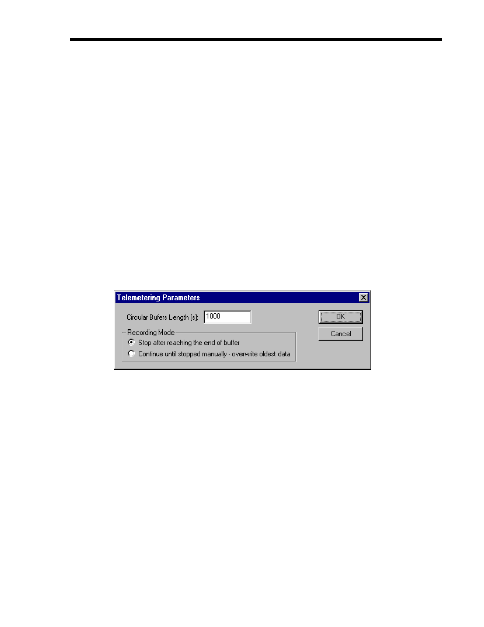
Entering the DataLink Telemetry Parameters
The final step in setting up the real time telemetry session is to set the DataLink II real time
recording parameters. These parameters are set by selecting the Recording Parameter menu
item found in the Telemetry main menu selection. The following dialog box will be displayed.
The first parameter Circular Buffer Length is used to set the amount of data to record in
seconds. The Recording Mode is used to determine whether the recording will stop when the
maximum record time is reached or whether the oldest data will be overwritten. For example if
a Circular Buffer Length of 1000 seconds is entered and stop after reaching end of buffer is
selected, the program will record data for 1000 seconds and stop. If continue until stopped
manually-overwrite oldest data is selected the program will continuously record until stopped
by the operator. Only the last 1000 seconds of data will be stored.