Telemetry "telemetry, Fu n c tio n – Futaba 4PLS 2.4GHz FHSS User Manual
Page 107
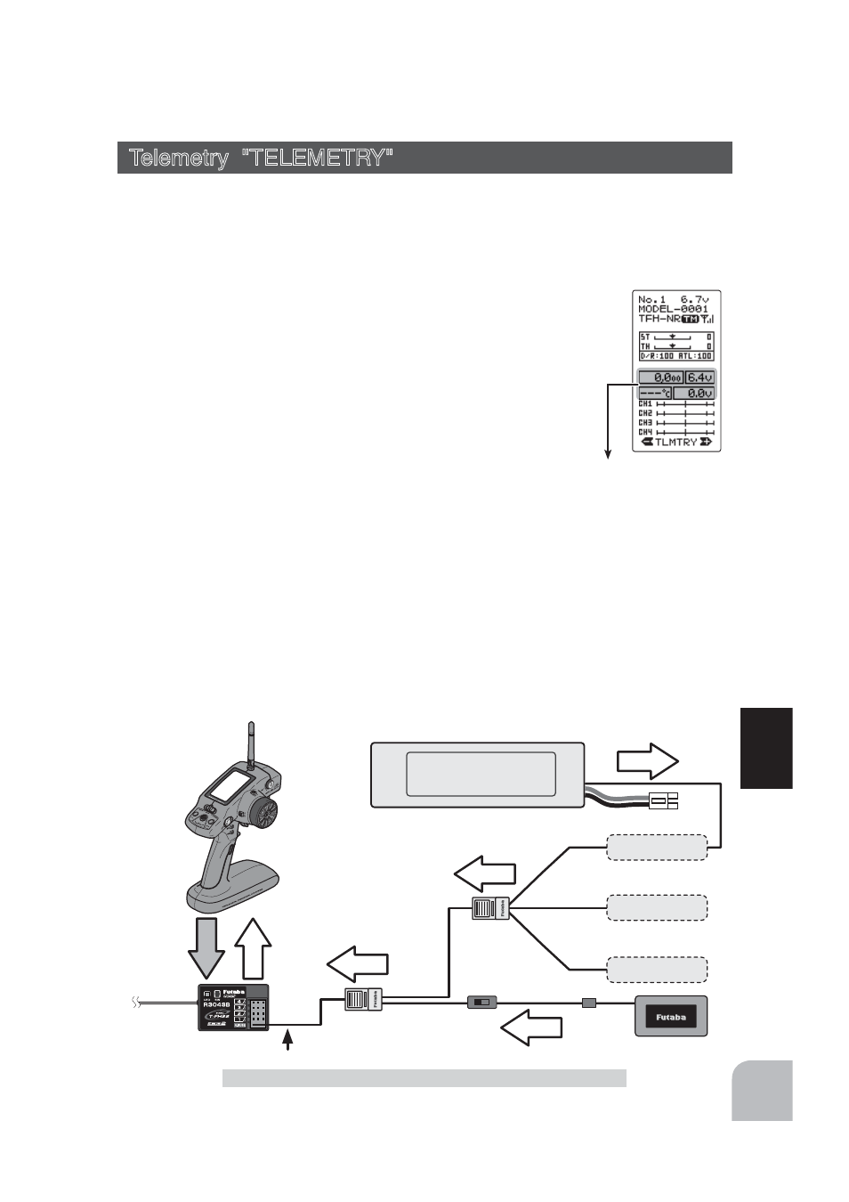
Telemetry info
(HOME screen)
107
Fu
n
c
tio
n
Info
Info
Info
Info
Signal
Info
Temperature
Sensor
RPM
Sensor
Voltage
Sensor
Battery voltage is displayed
at the transmitter.
Power batter y voltage is
displayed at the transmitter.
voltage
T-FHSS Receiver
Transmitter
Switch
Connect to S.BUS2 Connector
HUB
HUB
Temperature Sensor
(SBS-01T)
RPM Sensor
(SBS-01RM)
Voltage Sensor
(SBS-01V)
Telemetry "TELEMETRY"
Telemetry "TELEMETRY"
With the telemetry system, the running status can be displayed at the transmitter and al-
so recorded as a data log by mounting various sensor units to the chassis.
The telemetry related screens are only displayed when the T4PLS power switch is in the
PWR ON position. When the power switch is in the DISP position, the telemetry related
screens are not displayed.
The T4PLS displays four kinds of information on the HOME screen; re-
ceiver power source (battery) voltage, external power supply (drive bat-
tery) voltage, speed, and temperature.
*The telemetry function is compatible with only the T-FHSS system.
*The telemetry function requires a corresponding receiver (R304SB).
*Only T4PLS with R304SB ID registered have a telemetry display.
*Multiple sensors of the same type cannot be used.
The sensor data can be checked at the transmitter by connecting
the telemetry sensor sold separately to the S.BUS2 connector of
the R304SB receiver.
7KH¿JXUHLVDQH[DPSOHRIFRQQHFWLRQRIDWHOHPHWU\VHQVRU7KHGDWDRIXSWRWKHIRO-
lowing 3 types of sensors and the receiver power supply voltage can be transmitted by
using the 3-way extension cord or double extension cord sold separately.
The receiver power supply can also be connected to the S-BUS2 connector or each of
&+ĺ$UHFHLYHUSRZHUVXSSO\YROWDJHVHQVRULVXQQHFHVVDU\
*The S-BUS2 system exerts control by connecting multiple gyros, servos and other devices corresponding to one S-BUS2
connector. Each device is separately controlled by setting the channel No. or slot No. individually for each device.
A slot No. is also set for telemetry sensors. With the T4PLS system, each slot No. of a telemetry sensor must be set to its ini-
tial value. Since the slot No. can be changed for other aircraft type transmitters (T18MZ, etc.), sensors with changed slot No.
will not operate if not returned to their initial slot No. When using a sensor that is used with transmitters other than a T4PL,
whether or not the slot No. is set to the initial value given in the sensor instruction manual must be checked at the changed
transmitter (T18MZ, etc.). With the T4PLS, the set slot No. cannot be checked or changed.
Connection
diagram