Diagnostics, Iagnostics – Flintec FAD-40 User Manual
Page 51
FAD-40 Technical Manual, Rev. 1.06 December 2012
Page 51 of 52
12. D
IAGNOSTICS
In this test menu serial interface tests (RC-232C and/or RS-485) and load cell signal analog to digital
conversion and processing tests are performed sequentially.
For entering the diagnostics mode, press the setup switch before power on and release the switch after the
instrument is powered on. The instrument will go into the RS-232C RXD test mode which is indicated by lighted
LED and flashed Err LED as shown below. The status of LEDs on the front panel indicate the test steps
and the test result as described below. You can go to the next test by pressing the setup switch.
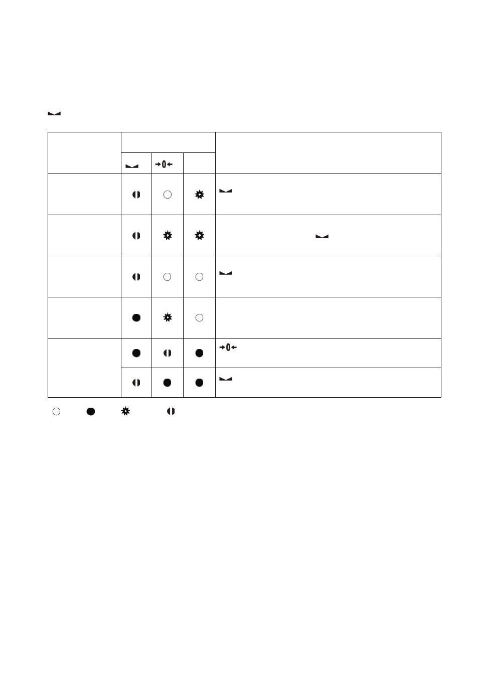
Test
LED’s Status
Description
Err
RS-232C RxD
(not for FAD-40
and FAD-40MB)
LED gets off 0.3 s after receiving any data. Press the
setup switch to go to the next test step.
RS-232C TxD
(not for FAD-40
and FAD-40MB)
„A‟ to „Z‟ characters are sent sequentially in 0.8 s intervals. If
the same data is received,
LED gets off for 0.3 s. Press
the setup switch to go to the next test step.
RS-485 RD
(for FAD-40 and
FAD-40MB only)
LED gets off for 0.3 s after receiving any data. Press the
setup switch to go to the next step.
RS-485 TD
(for FAD-40 and
FAD-40MB only)
„A‟ to „Z‟ characters are sent sequentially in 0.8 s intervals.
Press the setup switch to go to the next step.
Load cell signal
LED gets off while the load cell signal increases. Press
the setup switch to go to the next step.
LED gets off while the load cell signal decreases. Press
the setup switch to return to the RS-232C RxD test.
Off
On
Flash Off for 0.3 second
Table 12.1
– Diagnostics