Setup of digital output function, Setup of digital input function – Flintec FAD-40 User Manual
Page 19
FAD-40 Technical Manual, Rev. 1.06 December 2012
Page 19 of 52
I/O1:
Select function and polarity
for I/O1 (output only)
I/O2:
Select function and polarity
for I/O2
I/O3:
Select function and polarity
for I/O3
Setpoint entries: Enter setpoints.
Setpoint1 for I/O1, setpoint 2 for I/O2
and setpoint3 for I/O3.
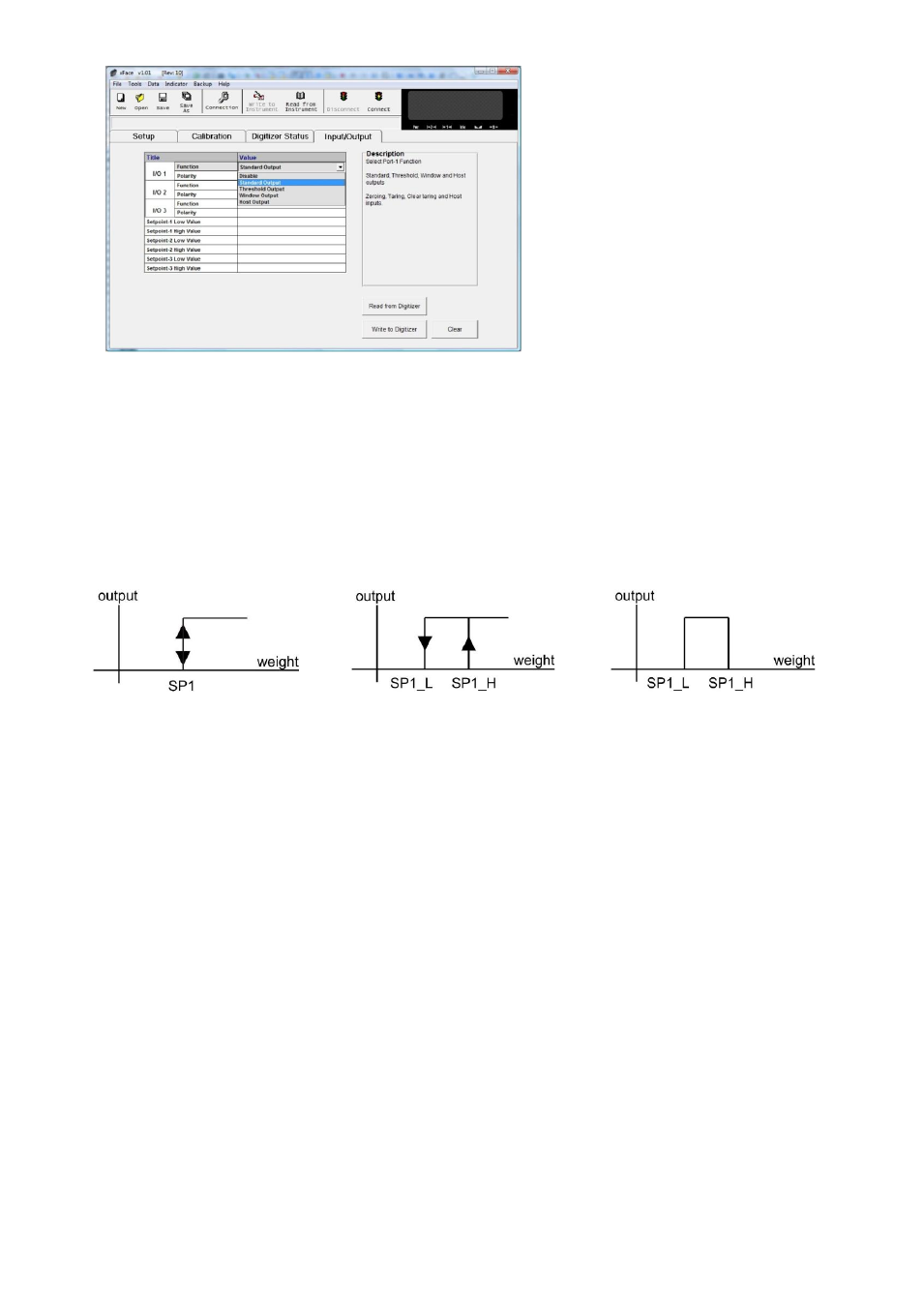
Figure 5.7
– Digital I/O Setup
Setup of Digital Output Function
I/O1, I/O2 and I/O3 can be set up with the output functions described below.
Standard output
(Setpoint without hysteresis):
Only one value is entered. The
output state is forced active (active
high or active low, selectable) when
the weight is higher than the
setpoint SP1, else the output is
passive.
Setpoint with hysteresis:
2 values are entered. The output
state is forced active when the
weight gets higher than the higher
setpoint value SP1_H. The output
state drops to passive state when
the weight gets lower than the
smaller setpoint value SP1_L.
Tolerance band:
2 setpoint values are entered. The
output is active when the weight is
between these two setpoints
(SP1_L and SP1_H).
Host Output: Output controlled over field bus commands. Refer to related field bus data structure.
Disable: The ouput will be disabled.
I/O Polarity: The output polarity can be defined for active high (default) or active low (inverses the output).
Enter the setpoint values for the selected output function. Host output needs no setpoint value. Click “Write to
Converter” to save the changes.
Setup of Digital Input Function
I/O2 and I/O3 can be set up with the input functions described below:
Zeroing
The input signal zeros the scale.
Taring
The input signal tares the scale.
Clear Tare
The input signal cleares the tare memory.
Host Input
Input controlled over field bus commands. Refer to related field bus data structure.
Disable
The input will be disabled.
I/O Polarity
The input polarity can be defined for active high (default setup) or active low (inverses the input).