Load cell connection, Digital i/o connection – Flintec FAD-40 User Manual
Page 11
FAD-40 Technical Manual, Rev. 1.06 December 2012
Page 11 of 52
poor ground can result in an unsafe and unstable operation. It is important that the instrument should not share
power lines with noise-generating equipment such as heavy load switching, motor control equipments,
inductive loads, etc. If the condition of the power line in the plant is poor, prepare a special power line and
grounding. Before interfering the instrument, turn off the power and wait at least for 30 seconds.
4.2.2.
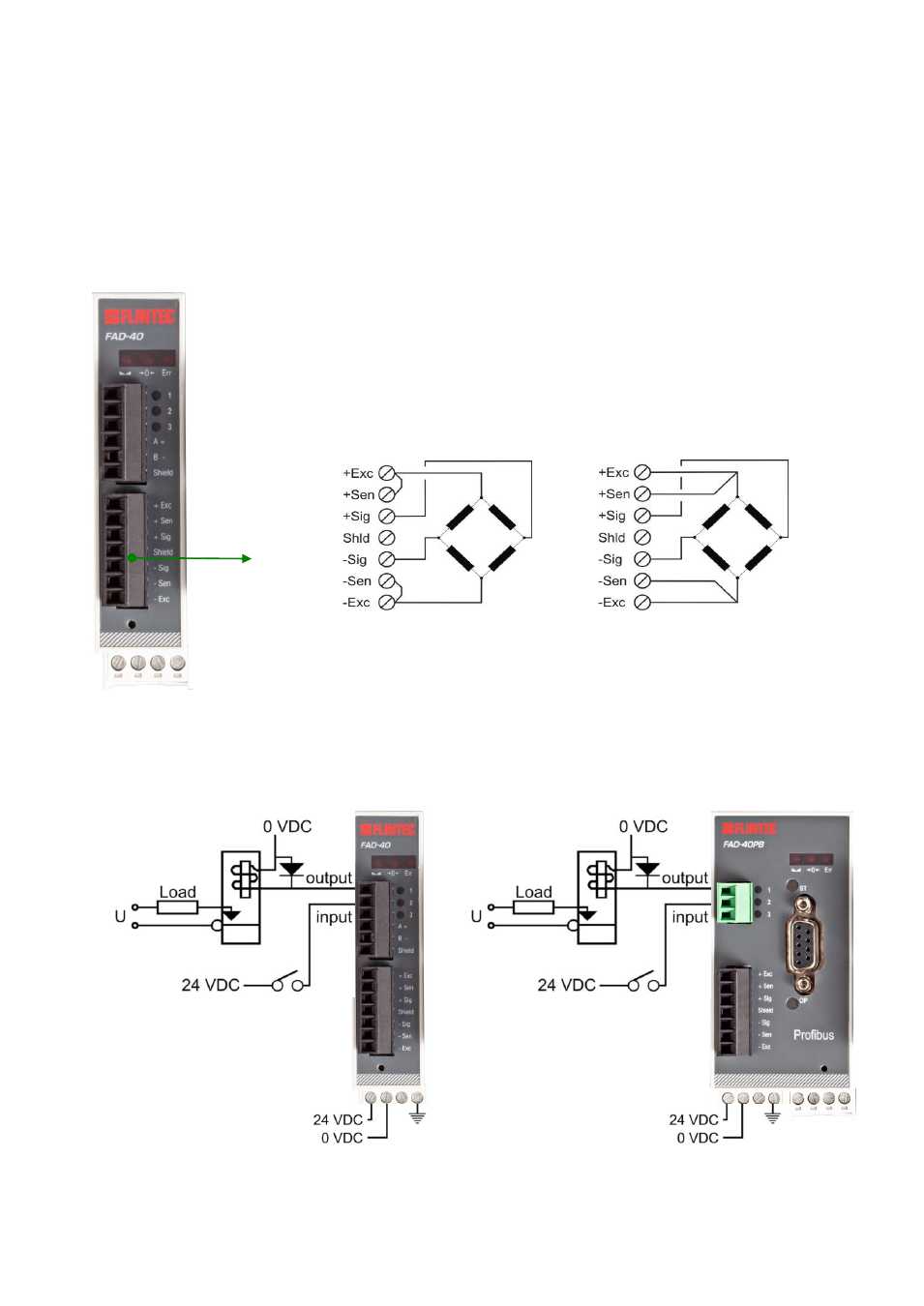
Load Cell Connection
To avoid damages, the load cell wiring should be made carefully before energizing the instrument. Load cell
connection details are shown below in figure 4.2. In 4-wire installations the sense and excitation pins with the
same polarity should be short circuited at the connector side. If you have a junction box in your system, use a 6
wire cable between FAD-40 and the junction box, and short circuit these pins at junction box for better
performance.
Load Cell
Connector
4 wire LC connection
6 wire LC connection
Warning: Connect the load cell cable shield to the reference ground or the
shield pin of the load cell connector.
Figure 4.2
– Load cell connection
4.2.3.
Digital I/O Connection
FAD-
40 instruments have the digital I/O connectors on the instrument‟s front. I/O1 is always an output, I/O2 and
I/O3 can be configured for input or output. The I/O connection diagram is shown in Figure 4.3
Figure 4.3
– Digital I/O connection