Explanation – Flintec FAD-40 User Manual
Page 27
FAD-40 Technical Manual, Rev. 1.06 December 2012
Page 27 of 52
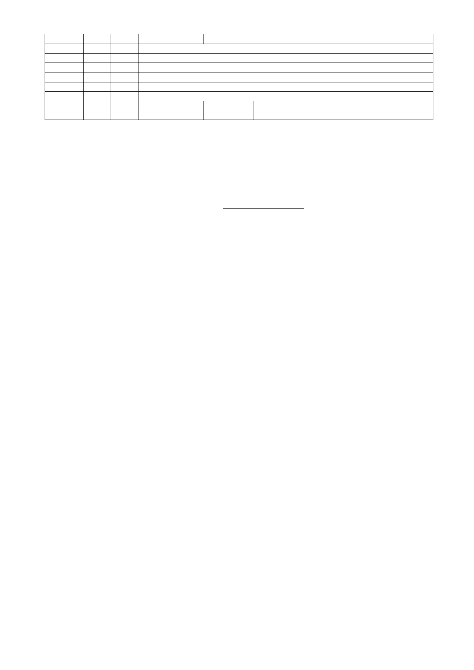
Address R/W
Word Command
Description
40021
R/W
2
Setpoint 1 Low for I/O1
40023
R/W
2
Setpoint 1 High for I/O1
40025
R/W
2
Setpoint 2 Low for I/O2
40027
R/W
2
Setpoint 2 High for I/O2
40029
R/W
2
Setpoint 3 Low for I/O3
40031
R/W
2
Setpoint 3 High for I/O3
40033
R/W
1
Save I/O settings 23205 (Dec)
Load 23205 to save and activate
I/O settings and setpoints
Note: Standard setpoint output function uses only setpoint low.
EXPLANATION
Attention: For hardware connection details, please refer to the related hardware descriptions in this manual.
In the two word registers the data is stored to the registers in big-endian format. The least significant word is
stored to the highest register address; and the most significant word is stored to the lowest register address.
Please find Modbus information in the web site of
Exception codes
1:
Function code is not supported.
2:
Out of address range
3:
Invalid value or wrong byte number
4:
Operation error
Examples:
Performing Read and Write operations according to hex system with the instrument set to address “0x01”.
Request weight data:
01,03,00,00,00,02,C4,0B
Answer of requested weight:
01,03,04,00,01,86,A0,38,4A
Weight is 100000
Request status data :
01,03,00,02,00,01,25,CA
Taring:
01,10,00,08,00,01,02,00,02,26,D9
Request tare data:
01,03,00,03,00,02,34,0B
Answer of requested tare:
01,03,04,00,00,27,10,E0,0F
Tare is 10000
Weight Mode Selection:
01,10,00,0D,00,01,02,00,04,A6,8E
Count in Unipolar Mode Selection:
01,10,00,0D,00,01,02,00,00,A7,4D
5 mV Input signal range selection:
01,10,00,0E,00,01,02,00,00,A7,7E
Load Medium (5) to Digital filter:
01,10,00,0F,00,01,02,00,05,66,AC
Request Calibration Status:
01,03,00,0C,00,01,44,09
Answer of requested Calibration Status:
01,03,02,00,01,79,84
Instrument is ready for calibration
Zero Calibration Command:
01,10,00,08,00,01,02,00,01,66,D8
Span Calibration with Span Value 50000:
01,10,00,09,00,03,06,00,DC,00,00,C3,50,B7,B0
Read digital I/Os:
01,03,00,11,00,01,D4,0F
Response of digital I/Os:
01,03,02,01,02,38,15
Output 1 and Output 2 is active.
Setup I/Os for Output:
01,10,00,12,00,02,04,82,81,00,83,4A,8B
I/O 1 = Standard, Active High;
I/O 2 = Setpoint with hysteresis, Active High;
I/O 3 = Tolerance window, Active High.
Setup I/Os for Input:
01,10,00,12,00,02,04,05,84,00,06,B3,9D
I/O 1 = Host Output, Active High
I/O 2 = Zeroing Input, Active Low
I/O 3 = Taring Input, Active Low
Load Setpoint 1 Low = 5000 and Set point 1 High = 6000:
01,10,00,14,00,04,08,00,00,13,88,00,00,17,70,6A,E2
Request Setpoint 1 Low and Setpoint 1 High values:
01,03,00,14,00,04,04,0D
Response of Setpoint 1 request:
01,03,08,00,00,17,70,00,00,1B,58,DC,31
Setpoint 1 Low = 6000 and Setpoint 1 High = 7000.
Save and activate I/O settings and Set points:
01,10,00,20,00,01,02,5A,A5,5B,EB