Electrical connections, Interfacing, Setup and calibration – Flintec FAD-40 User Manual
Page 37: Modbus rtu (for fad-40mb only)
FAD-40 Technical Manual, Rev. 1.06 December 2012
Page 37 of 52
6.2. Electrical Connections
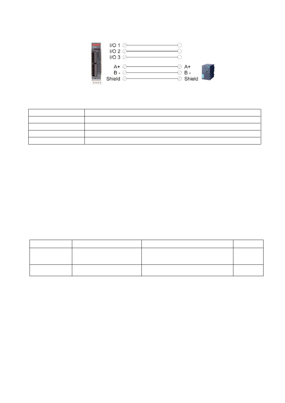
RS-485 connection is shown in figure 6.2.
Figure 6.2
– FAD-40 / FAD-40MB serial interface connection
RS-485 Serial Interface
Use
Interfacing with PC or PLC, setup via xFace
Data format
BSI (default for FAD-40), Modbus RTU (for FAD-40MB only, default)
Baud rate
1200 / 2400 / 4800 / 9600 (Default) / 19200 / 38400 / 57600 bps
Length and parity
8 None 1 (default), 7 odd 1, 7 even 1
Start / Stop bits
1 start bit and 1 stop bit
Warning: Connect the shield to the reference ground.
Warning: Disconnect xFace PC software for Modbus-RTU interfacing
Load Cell Connection
See chapter 4.2.2
Digital I/O Connection
See chapter 4.2.3
Power Supply Connection
See chapter 4.2.1
6.3. Interfacing
FAD-40 and FAD-40MB instruments have one serial interface connector on the front of the instrument: RS-485.
The table below describes the data format for interfacing the peripherals and their application:
Data Format
Description
Application
Hardware
BSI
Demand interface on BSI
Serial Interface format.
Refer to chapter 5.10
Master
– Slave data interfacing with
PLC or PC.
RS-485
Modbus RTU
(FAD-40MB only)
Modbus RTU interfacing.
Refer to chapter 5.11
Interfacing with PLC.
RS-485
Table 6.1
– Data output interfacing
Attention: Please disable the interface if not used to increase the performance of the instrument.
6.4. Setup and Calibration
FAD-40 and FAD-40MB instruments are set up and calibrated by xFace. The A/D Converter settings are very
important for a good weighing performance. Please refer to chapter 5.3.
6.5. Modbus RTU (for FAD-40MB only)
If the FAD-40MB instrument is setup for Modbus, it can be used as a Modbus RTU slave in a RS-485
communication netw
ork. Function codes „0x03‟ and „0x10‟ are supported. For RS-485 setup please refer to
chapter 5.3.2, for the Modbus data structure please refer to chapter 5.11.