Digilent 410-178P-KIT User Manual
Page 21
Atlys Reference Manual
www.digilentinc.com
page 21 of 22
Copyright Digilent, Inc. All rights reserved. Other product and company names mentioned may be trademarks of their respective owners.
VHDC Connector Pinout
IO1-P: U16
IO1-N: V16
IO11-P: U10
IO11-N: V10
IO2-P: U15
IO2-N: V15
IO12-P: R8
IO12-N: T8
IO3-P: U13
IO3-N: V13
IO13-P: M8
IO13-N: N8
IO4-P: M11
IO4-N: N11
IO14-P: U8
IO14-N: V8
IO5-P: R11
IO5-N: T11
IO15-P: U7
IO15-N: V7
IO6-P: T12
IO6-N: V12
IO16-P: N7
IO16-N: P8
IO7-P: N10
IO7-N: P11
IO17-P: T6
IO17-N: V6
IO8-P: M10
IO8-N: N9
IO18-P: R7
IO18-N: T7
IO9-P: U11
IO9-N: V11
IO19-P: N6
IO19-N: P7
IO10-P: R10
IO10-N: T10
IO20-P: U5
IO20-N: V5
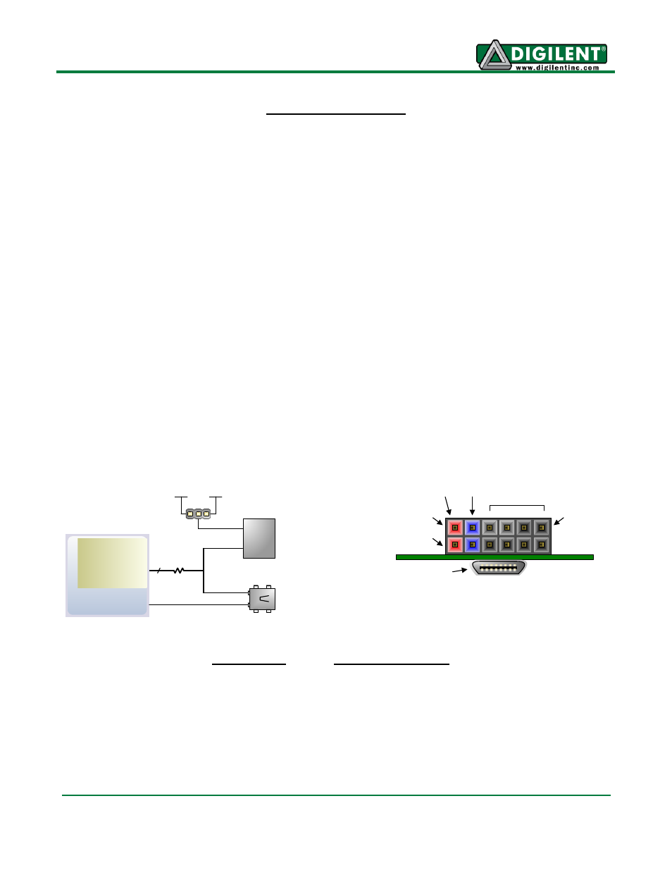
The Pmod connector is a 2x6 right-angle, 100-mil female connector that mates with standard 2x6 pin
headers available from a variety of catalog distributors. The 12-pin Pmod connector provides two VCC
signals (pins 6 and 12), two Ground signals (pins 5 and 11), and eight logic signals. VCC and Ground
pins can deliver up to 1A of current. Jumper JP12 selects the Pmod Vcc voltage (3.3V or 2.5V) in
addition to selecting the VHDC voltage. Pmod data signals are not matched pairs, and they are routed
using best-available tracks without impedance control or delay matching.
On the Atlys board, the eight Pmod signals are shared with eight data signals routed to an HDMI type
D connector. The HDMI connector, located immediately beneath the Pmod connector on the reverse
side of the board, includes an I2C bus and conforms to the HDMI type D pinout specification, so it can
be used as a secondary HDMI output port. A type D to type A HDMI cable may be required, and is
available from Digilent and a variety of suppliers.
Pmod
Signals (x8)
Bank 2
Pin 1
Pin 12
Pin 6
8 signals
VCC GND
VCC
Pmod
Connector
Pmod Connectors
– front
view as loaded on PCB
50
Ω
3.3V
2.5V
JP12
HDMI Type D
connector
HDMI-D
Connector
8
I2C Bus
Spartan-6
Pmod Pinout
HDMI Type D Pinout
JA1:
T3
D0+: R3
SCL: C13
JA2:
R3
D0-: T3
SDA: A13
JA3:
P6
D1+: T4
CEC: Vcc
JA4:
N5
D1-: V4
RES: Vcc
JA7:
V9
D2+: N5
HPD: 5V
JA8:
T9
D2-: P6
DDC: GND
JA9:
V4
CLK+: T9
JA10:
T4
CLK-: V9