Basic i/o, Spartan-6 – Digilent 410-178P-KIT User Manual
Page 19
Atlys Reference Manual
www.digilentinc.com
page 19 of 22
Copyright Digilent, Inc. All rights reserved. Other product and company names mentioned may be trademarks of their respective owners.
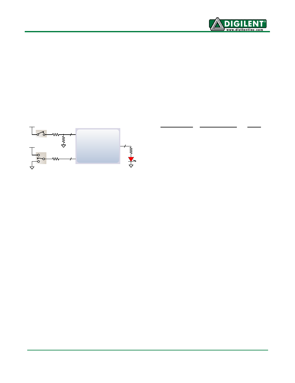
Spartan-6
Slide Switches
10K
10K
10K
LEDs
390
8
6
8
Pushbuttons
Basic I/O
The Atlys board includes six pushbuttons, eight slide switches, and eight LEDs for basic digital input
and output. One pushbutton has a red plunger and is labeled "reset" on the PCB silkscreen
– this
button is no different than the other five, but it can be used as a reset input to processor systems. The
buttons and slide switches are connected to the FPGA via series resistors to prevent damage from
inadvertent short circuits. The high efficiency LED anodes are connected to the FPGA via 390-ohm
resistors, and they will brightly illuminate with about 1mA of current when a logic high voltage is
applied to their respective I/O pin.
Pushbuttons
Slide Switches
LEDs
BTNU: N4
SW0: A10
LD0: U18
BTNC: F5
SW1: D14
LD1: M14
BTNR: F6
SW2: C14
LD2: N14
BTNL: P4
SW3: P15
LD3: L14
BTND: P3
SW4: P12
LD4: M13
BRST: T15 SW5: R5
LD5: D4
SW6: T5
LD6: P16
SW7: E4
LD7: N12