Usb-uart bridge (serial port), Usb hid host – Digilent 410-178P-KIT User Manual
Page 16
Atlys Reference Manual
www.digilentinc.com
page 16 of 22
Copyright Digilent, Inc. All rights reserved. Other product and company names mentioned may be trademarks of their respective owners.
Spartan-6
P17
PIC24FJ192
K_CLK
N15
“HOST”J13
2
N18
P18
K_DAT
M_CLK
M_DAT
R13
R15
DIN
CLK
FPGA Serial
programming
PS/2 Keyboard
PS/2 Mouse
DCMs provide the four phases of the input frequency (0º, 90º, 180º, and 270º), a divided clock that
can be the input clock divided by any integer from 2 to 16 or 1.5, 2.5, 3.5... 7.5, and two antiphase
clock outputs that can be multiplied by any integer from 2 to 32 and simultaneously divided by any
integer from 1 to 32.
PLLs use VCOs that can be programmed to generate frequencies in the 400MHz to 1080MHz range
by setting three sets of programmable dividers during FPAG configuration. VCO outputs have eight
equally-spaced outputs (0º, 45º, 90º, 135º, 180º, 225º, 270º, and 315º) that can be divided by any
integer between 1 and 128.
USB-UART Bridge (Serial Port)
The Atlys includes an EXAR USB-UART bridge to allow PC applications to communicate with the
board using a COM port. Free drivers allow COM-based (i.e., serial port) traffic on the PC to be
seamlessly transferred to the Atlys
board using the USB port at J17
marked UART. The EXAR part
delivers the data to the Spartan-6
using a two-wire serial port with
software flow control (XON/XOFF).
Free Windows and Linux drivers can
be downloaded from
Typing the EXAR part number “XR21V1410” into the search box
will provide a link to the XR21V1410’s land page, where links for current drivers can be found. After
the drivers are installed, I/O commands from the PC directed to the COM port will produce serial data
traffic on the A16 and B16 FPGA pins.
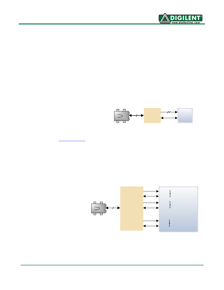
USB HID Host
A Microchip PIC24FJ192 microcontroller provides the Atlys board with USB HID host capability.
Firmware in the MCU microcontroller can drive a mouse or a keyboard attached to the type A USB
connector at J13 labeled "Host".
Hub support is not currently
available, so only a single mouse
or a single keyboard can be used.
The PIC24 drives four signals into
the FPGA
– two are used as a
keyboard port following the
keyboard PS/2 protocol, and two
are used as a mouse port
following the mouse PS/2
protocol.
Two PIC24 I/O pins are also
connected to the FPGA’s two-wire
serial programming port, so the FPGA can be programmed from a file stored on a USB memory stick.
To program the FPGA, attach a memory stick containing a single .bit programming file in the root
directory, load JP11, and cycle board power. This will cause the PIC processor to program the FPGA,
and any incorrect bit files will automatically be rejected.
A16
TXD
B16
Micro-USB
J17
“UART”
2
RXD
200
Ω
Spartan-6
XR21V1410