14 audio – Digilent 410-279P-KIT User Manual
Page 22
ZYBO™ FPGA Board Reference Manual
Copyright Digilent, Inc. All rights reserved.
Other product and company names mentioned may be trademarks of their respective owners.
Page 22 of 26
Zynq
V16
Y16
P16
BTN3
BTN2
BTN1
3.3V
LEDs
Slide
Switches
3.3V
Buttons
R18
BTN0
T16
W13
P15
G15
SW1
SW3
SW2
SW0
LD3
LD2
LD1
LD0
D18
G14
M15
M14
PL
PS
MIO51
BTN5
MIO50
BTN4
LD12
MIO7
3.3V
MIO
Buttons
MIO
LED
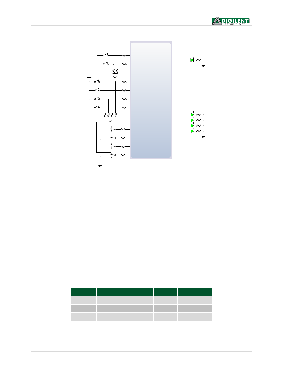
Figure 14. ZYBO GPIO.
The high-efficiency LEDs are anode-connected to the Zynq via 330-ohm resistors, so they will turn on when a logic
high voltage is applied to their respective I/O pin. Additional LEDs that are not user-accessible indicate power-on,
FPGA programming status, and USB and Ethernet port status.
The LED and two pushbuttons attached directly to the PS are accessed using the Zynq GPIO controller. This core is
described in full in Chapter 14 of the Zynq Technical Reference Manual.
14 Audio
An Analog Devices SSM2603 Audio Codec provides integrated digital audio processing to the Zynq-7000 AP SoC. It
allows for stereo record and playback at sample rates from 8 kHz to 96 kHz.
On the analog side, the codec connects to three 3.5 mm standard audio jacks. There are two inputs: a mono
microphone and a stereo line in. There is one stereo output, the headphone jack. Analog power is provided by a
dedicated linear power supply (IC6).
Audio Jack Description
Channels Color
SSM2603 pin
J5
Headphone Out Stereo
Black
L/RHPOUT
J6
Microphone In
Mono
Pink
MICIN, MICBIAS
J7
Line In
Stereo
Light Blue L/RLINEIN
Table 7. Analog audio signals.