Digilent 410-279P-KIT User Manual
Page 15
ZYBO™ FPGA Board Reference Manual
Copyright Digilent, Inc. All rights reserved.
Other product and company names mentioned may be trademarks of their respective owners.
Page 15 of 26
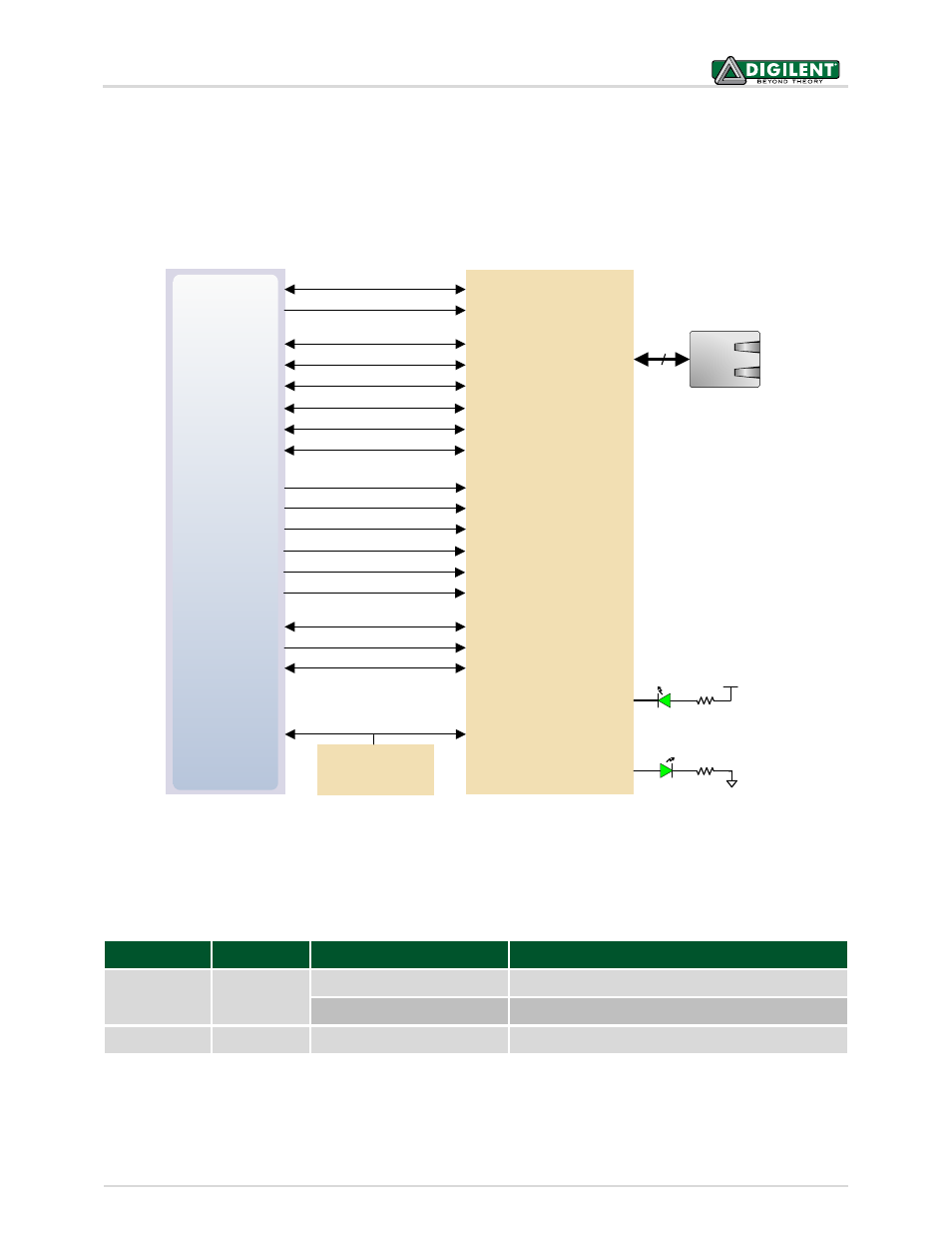
management. The auxiliary interrupt (INTB) and reset (PHYRSTB) signals connect to PL pins to be accessed via
EMIO. The connection diagram can be seen on Fig. 7.
After power-up the PHY starts with Auto Negotiation enabled, advertising 10/100/1000 link speeds and full duplex.
If there is an Ethernet-capable partner connected, the PHY automatically establishes a link with it, even with the
Zynq not configured.
MIO24
MIO52
MIO53
Zynq-7
MDIO
8
MDC
MIO23
RXD0/SELRGV
Realtek RTL8211E
RJ-45 with
magnetics
RXD1/TXDLY
RXD2/AN0
MIO25
MIO27
MIO26
RXD3/AN1
RXCTL/PHY_AD2
RXC
MIO22
MIO18
MIO17
TXD0
TXD1
TXD2
MIO19
MIO21
MIO20
TXD3
TXCTL
TXC
MIO16
E17
F16
INTB
PHYRSTB
CLK125
L16
DSC1121CE5
50 MHz
Oscillator
CKXTAL1
PS_CLK
ACT LED (LD7)
LINK LED (LD6)
LED0/PHY_AD0
LED1/PHY_AD1
Figure 7. Ethernet PHY signals.
Two status indicator LEDs are on-board near the RJ-45 connector that indicate traffic (LD7) and valid link state
(LD6). Table 5 shows the default behavior.
Function
Designator
State
Description
LINK
LD6
On
Link 10/100/1000
Blinking 0.4s ON, 2s OFF
Link, Energy Efficient Ethernet (EEE) mode
ACT
LD7
Blinking
Transmitting or Receiving
Table 5. Ethernet status LEDs.
The Zynq incorporates two independent Gigabit Ethernet Controllers. They implement a 10/100/1000 half/full
duplex Ethernet MAC. Of these two, GEM 0 can be mapped to the MIO pins where the PHY interfaces. Since the