6-6. adjusting the notch, 6-7. digital display calibration – Kenwood TS-850S User Manual
Page 76
Attention! The text in this document has been recognized automatically. To view the original document, you can use the "Original mode".
linear’s relay control line to pin 4. The relay in this
transceiver is capable of handling 100V DC at 500 mA.
6-6-6. Adjusting the NOTCH
VR16
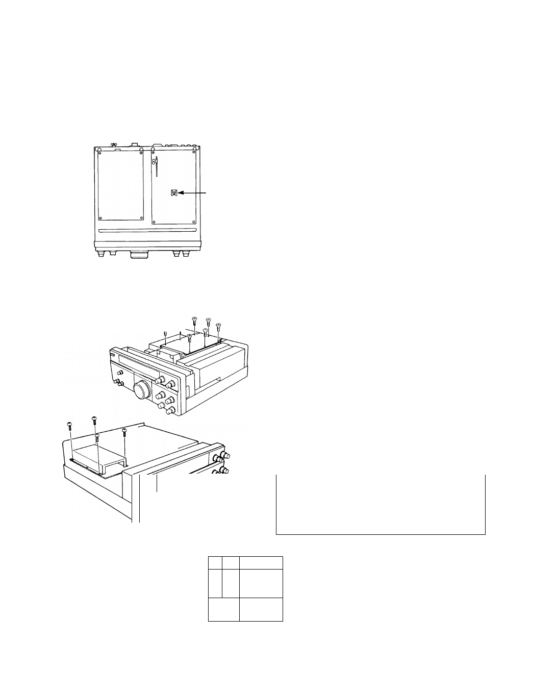
6-6-7. Digital display calibration
f-
Note
The TL-922/922A is NOT designed for Full Break-in
operation. Attempting operation of the linear in this
mode might lead to damage in the linear amplifier.
1. Rotate the tuning knob so that a stable signal of
about S9 is received in USB mode and the beat
frequency of the audio output is about 1.5 kHz.
2. Rotate the HIGH side of the SLOPE TUNE control
fully
clockwise
and
the
LOW
side
fully
counterclockwise.
3. Activate the NOTCH switch, and rotate the NOTCH
control to minimize the audio output.
4. Adjust VR16 to further reduce the audio output.
5. Perform steps 3 and 4 repeatedly.
6. The best point is where the audio output does not
change.
1. Remove the case.
2. Remove the shield cover of the final unit.
3. Remove the CAR unit.
4. Plug the accessory calibration cable to any one of the
CAL pins on the PLL unit.
Plug the other end of the calibration cable to CAL Pin
on the ANT unit.
5. Connect your antenna and tune to WWV. Select
“TUNE” on the front panel key pad.
6. Using a small flat bladed screwdriver adjust trimmer
capacitor TC5 on the PLL unit for zero beat. Zero
beat is the point where the two audio tones match
perfectly.
7. The reference frequency has been calibrated
correctly.
8. Remove the calibration cable.
Note
This equipment was calibrated at the factory using an
external frequency standard and should not require
Calibration
recalibration. Do not attempt recalibration unless it is
necessary.
1—L-q 4
1 OCAL
O
O
O
0
CAL
■ £[ Tc 6 1^
66