Transmission), O o o – Kenwood TS-850S User Manual
Page 34
Attention! The text in this document has been recognized automatically. To view the original document, you can use the "Original mode".
MODE key
Press the LSB/USB key to
alternate between LSB and
USB.
RIT/XIT switch/control
SQL(Squelch) control
NOTCH switch/control
NB switch/control
NB1 : For pulse type noise,
such as generated by
automotive ignition
systems.
NB2 : Noise blanker 2 is
used for long duration
pulse noise, like the
“woodpecker”.
RF gain control
This control should be all the
way to the right.
TONE control
Turn the control to increase
or decrease the tone.
SLOPE TUNE control
93385;—
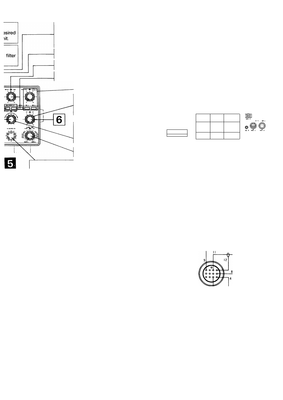
^___ 0^ © © ©o o o he tuning z (1 Hz ling. M.CH/VFO CH control This control is used to kHz steps during VFO This control is also used to select the desired memory during Memory Channel Operation. LINEAR AMP switch Activates the relay for the linear amplifier control. If the slowly, you may need to 1 © ACC 2 connector Connect the ACC 2 connector. ■4 ■- Standby (TRANSMISSION) Q Connect the communication terminal signal line to the ACC 2 connector on the rear. Q Turn on the DC power supply and then turn the transceiver’s power switch ON. Q A frequency is shown in the display. D Select LSB or USB with the MODE key. Q Enter the desired frequency. Before transmitting check the frequency for activity so that you do Q Press the METER key until the ALC meter lights. B Enter a transmit command from the communication terminal (generally, from the keyboard), and adjust the MIC gain control so that the meter deflection is within the ALC zone. Moduration GND AF INPUT Notes 2. If the output of the terminal unit causes the ALC meter to register above the recommended limits even with the MIC gain control turned all the way down you should reduce the output of the terminal unit. Excessive signal levels can
change the frequency in 10
operations.
channel
linear amplifier relay operates
make a retry. Check the
TNC parameter setting.
Connect the data communica
tions devices.
not interrupt another QSO.
output
1. Follow the instructions contained in your terminal units operating manual for the correct settings before you start transmitting.
cause distortion! If the terminal unit output level is fixed you should add a potentiometer between the transceiver and
the terminal unit. (Refer to Section 6-4-4.)