1-2. rear panel – Kenwood TS-850S User Manual
Page 17
Attention! The text in this document has been recognized automatically. To view the original document, you can use the "Original mode".
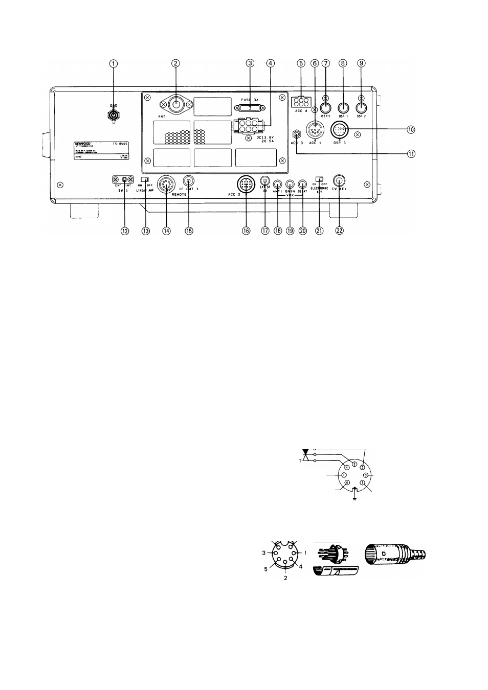
4-1-2. Rear Panel
©GND (Ground) terminal
To prevent electric shock, as well as RFI and BCl,
connect the transceiver to a good earth ground.
(D
ANT (Antenna) connector
This connector should be attached to a suitable
antenna for transmitting and receiving. The antenna
cable should be 50-ohm coax, terminated with a PL-
259 connector.
©FUSE
Power fuse for the ACC 4 connector.
@ DC power connector
This is used to connect the DC power supply.
© ACC 4 connector
The optional AT-300 may be connected here.
©ACC 1 connector
The optional DSP-100 or the optional IF-232C is
connected here.
© RTTY terminal
For connection to an RTTY interface unit, (direct
FSK keying) The terminal is equipped the short pin
plug for the factory.
©DSP 1 terminal
The optional DSP-100 is connected here.
® DSP 2 terminal
The optional DSP-100 is connected here.
(© DSP 3 connector
The optional DSP-100 is connected here.
©ACC 3 terminal
This is used to connect the remote controller.
® SW1 switch
This transceiver has a cover on the back to protect
against misoperation. To connect the external
antenna tuner to this unit, remove the cover and
slide switch SW1 to EXT. The built-in antenna tuner
will then not operate.
© LINEAR AMP switch
Activates the internal keying relay for linear amplifier
control.
© REMOTE connector
This connector is used when a linear amplifier is
used.
Control relay p
From standby switch
(PTT circuit for foot switch)
+ 12 VDC ON transmit
max. 10 mA
Speaker output
ALC input
GND'
View from cord
7. ^
6
Internal wiring
aaa—w-
© IF OUT 1 terminal
This terminal is for the band scope of the station
monitor.
IF 1 is for connection to the SM-230 for Pan Display.
(8.83 MHz)
17