Figure 2-6 – Cisco 5000 Series User Manual
Page 38
S e n d d o c u m e n t a t i o n c o m m e n t s t o n x 5 0 0 0 - d o c f e e d b a c k @ c i s c o . c o m
2-6
Cisco Nexus 5000 Series Hardware Installation Guide
OL-15902-01
Chapter 2 Cisco Nexus 5000 Series Overview
Cisco Nexus 5020 Switch
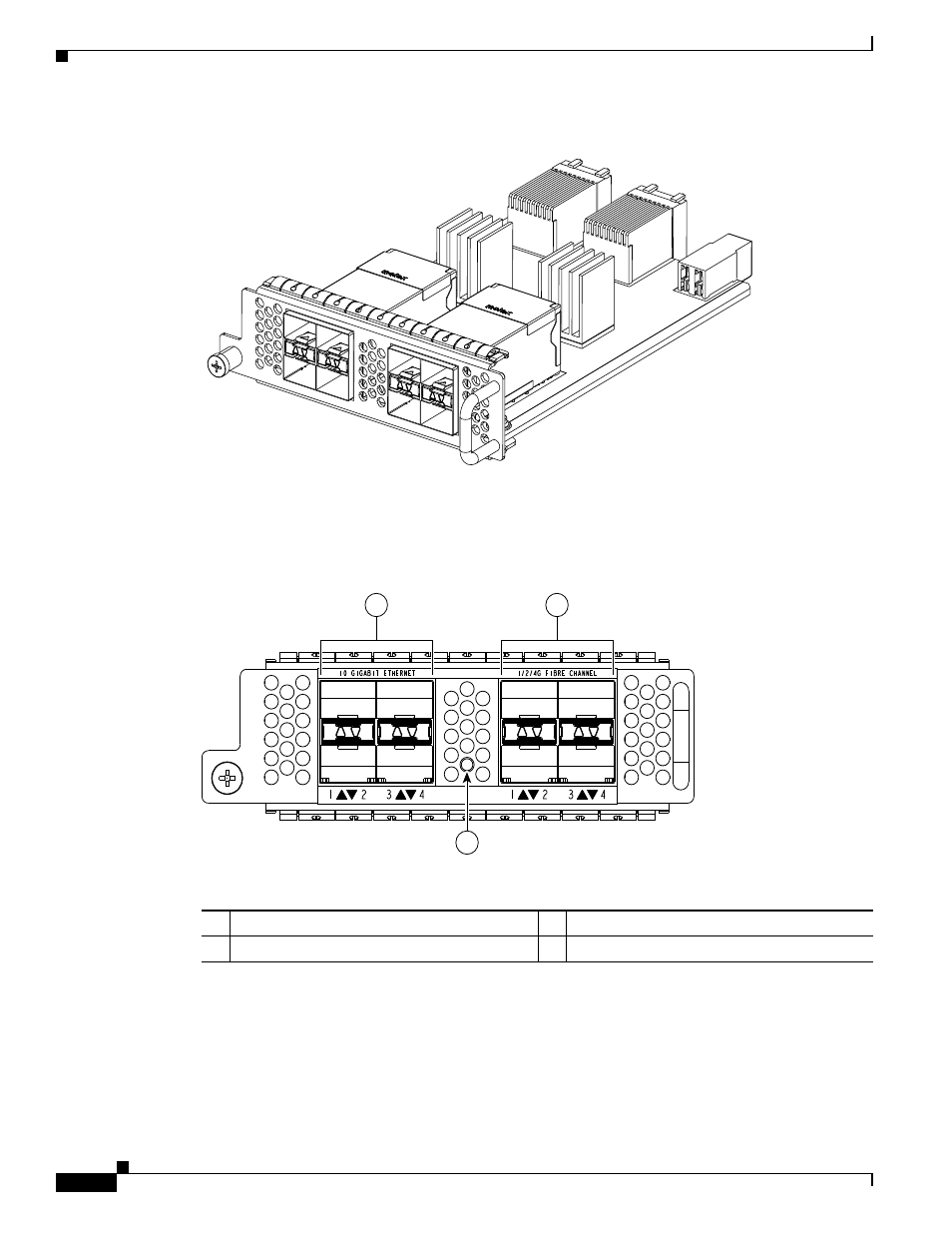
Figure 2-6
Fibre Channel Plus Ethernet Expansion Module
shows the front of the Fibre Channel plus Ethernet expansion module.
shows how
ports are numbered on the Fibre Channel plus Ethernet expansion module.
Figure 2-7
Front View of the Fibre Channel Plus Ethernet Expansion Module f
See
for an illustration of how ports are grouped and numbered on the Fibre Channel plus
Ethernet expansion module.
186384
1
2
3
4
1
2
3
4
10 GIGABIT ETHERNET
1/2/4G FIBRE CHANNEL
186258
1
3
2
1
Four 10-Gigabit Ethernet ports
3
Four 1-, 2-, 4-Gbps Fibre Channel ports
2
Module LED