Carl Goldberg GBGA0055 User Manual
Page 27
27
4.
■
■
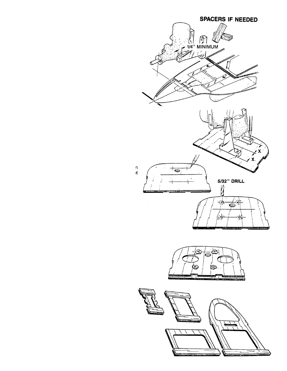
Position the ‘DRIVE WASHER,” of your engine over the
drive washer on the plan.
■
■
Place the MOTOR MOUNT against the firewall over the
plan.You may require spacers to accomplish the proper
position.
■
■
Tack glue the engine to the mounts.
NOTE:
MAKE SURE THAT THIS DIMENSION IS AT LEAST
1/4”. If not, use basswood spacers between the firewall
and the motor mounts.
5.
■
■
Place the motor assembly over the “AF” side of the
firewall.
■
■
Measure 1/2 of the total distance between the mounts,
from the scribe mark on the firewall to one of the
mounts.
■
■
With the holes on the vertical scribe marks on the
firewall, mark all four mounting bracket locations.
■
■
Drill a 5/32” hole at each location.
■
■
Turn the firewall over and insert the four 6-32 blind nuts.
Seat them with a soft hammer blow.
■
■
Coat the edges of the nut with JET GLUE. Be careful
to not get glue in the threads. Put the assembly aside
for now.
6.
■
■
Locate, glue, and trim the 1/8 X 1/2” balsa doublers to
the four formers, “D,” “E,” “F” and the SLANT former.