Carl Goldberg GBGA0055 User Manual
Page 11
11
3.
■
■
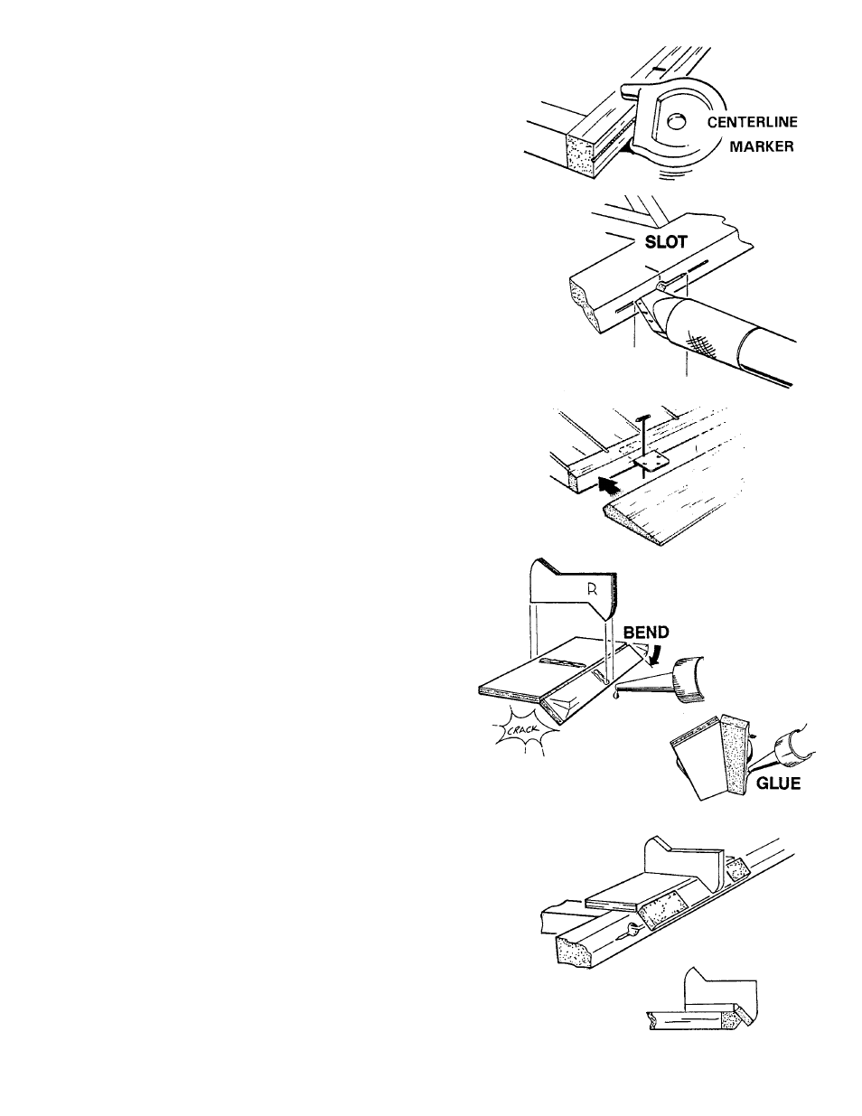
Using the centerline tool, scribe the centerline onto the
rudder post, the fin post, the hinge line of the stabilizer,
and onto both elevators
4.
■
■
Carefuly cut a slot approximately 1/2” deep and slightly
wider than the hinge, using your favorite knife blade.
5.
■
■
After all slots have been made, mark the center of your
hinge and insert a pin (see illus.) This will hold the
hinge in place while sliding the matching part (aileron,
etc.) onto the JET HINGE.
DO NOT GLUE!
■
■
With both surfaces hinged and assembled, check the
alignment. For good control response, the hinge gap
should be as small as possible, but
s h o u l d
allow for full deflection when needed.
Remove the hinges.
6.
■
■
Assemble the two bevel tools and install a strip of
medium grit sandpaper, as shown.
7.
■
■
Using the tool marked “R,” bevel the rudder-side of the
hingeline to a point at the centerline. You may want to
bevel near the air balance with a knife, if you can’t use
the tool in the corner.
■
■
Using the tool marked “AE,” bevel the elevators to a
point at the centerline.
8.
■
■
Temporarily hinge the rudder/fin and the stab/elevators
to check the surface alignment and to round the
perimeter of the assemblies.