Constructing the fuselage (36 steps) – Carl Goldberg GBGA0055 User Manual
Page 26
26
1.
■
■
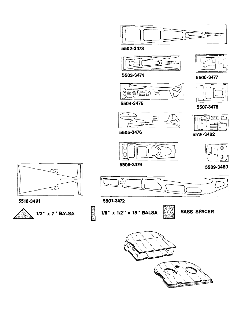
Gather all of the par ts needed to construct the
FUSELAGE. They include:
(2) D/C SHT. 5501 PLY SIDES
PT. #3475
(1) D/C SHT. 5502 PLY FUSE BOTTOM
PT. #3473
(1) D/C SHT. 5503 PLY
PT. #3474
CONTAINING TOP & BACKUPS
(1) D/C SHT. 5504 PLY
PT. #3475
CONTAINING DOUBLER, TRIPLER, FORMERS &
FUEL TANK TRAY
(1) D/C SHT. 5505 PLY
PT. #3476
CONTAINING DOUBLER, TRIPLER & FRMRS
(1) D/C SHT. 5506 PLY FRMRS & GAUGES
PT. #3477
(1) D/C SHT. 5507 PLY FORMERS
PT. #3478
(1) D/C SHT. 5508 PLY FORMERS
PT. #3479
(1) D/C SHT. 5509 PLY FIREWALL
PT. #3480
(1) D/C SHT. 5518 PLY TURTLEDECK
PT. #3481
(1) 1/32” PLY FRONT/TOP SHEET
PT. #4602
(1) BASS WING MOUNTING BLOCK
PT. #4372
(1) 1/4” PLY LANDING GEAR BLOCK
PT. #4373
(2) BASS MOTOR SPACER
PT. #4374
(1) 1/2” x 7” BALSA GUSSET
PT. #4217
(2) 1/8 x 1/2 x 18” BALSA STICK
PT. #4376
(6) 6-32 BLIND NUT
PT. #1124
(6) 6-32 x 1-1/4” SOCKET HD. SCREW
PT. #1024
(2) #6x3/4” WASHER
PT. #1144
(4) #6 x 3/4” SHT. METAL SCREW
PT. #1082
(2) MAIN LANDING GEAR WIRE
PT. #1322
(2) MOTOR MOUNT
PT. #1466
2.
■
■
Carefully remove the parts from the die sheets and
lightly sand the rough edges of each part.
3.
■
■
With the scribe lines exposed, glue FIREWALL
FORMER “AF” to the other firewall half. Make sure the
top and side edges match. Note the bottom offset fit.
Tape together and allow the assembly to dry on a flat
surface.
■
■
Drill a 3/8” diameter hole at the center mark.
CONSTRUCTING THE FUSELAGE (36 Steps)