Carl Goldberg GBGA0055 User Manual
Page 16
16
8.
■
■
Position the shaped L.E. onto the support tabs. Make
sure that the beveled/notched end is in line with the
wing centerline. Use a drafting triangle to project the
wing centerline to the L.E. end.
■
■
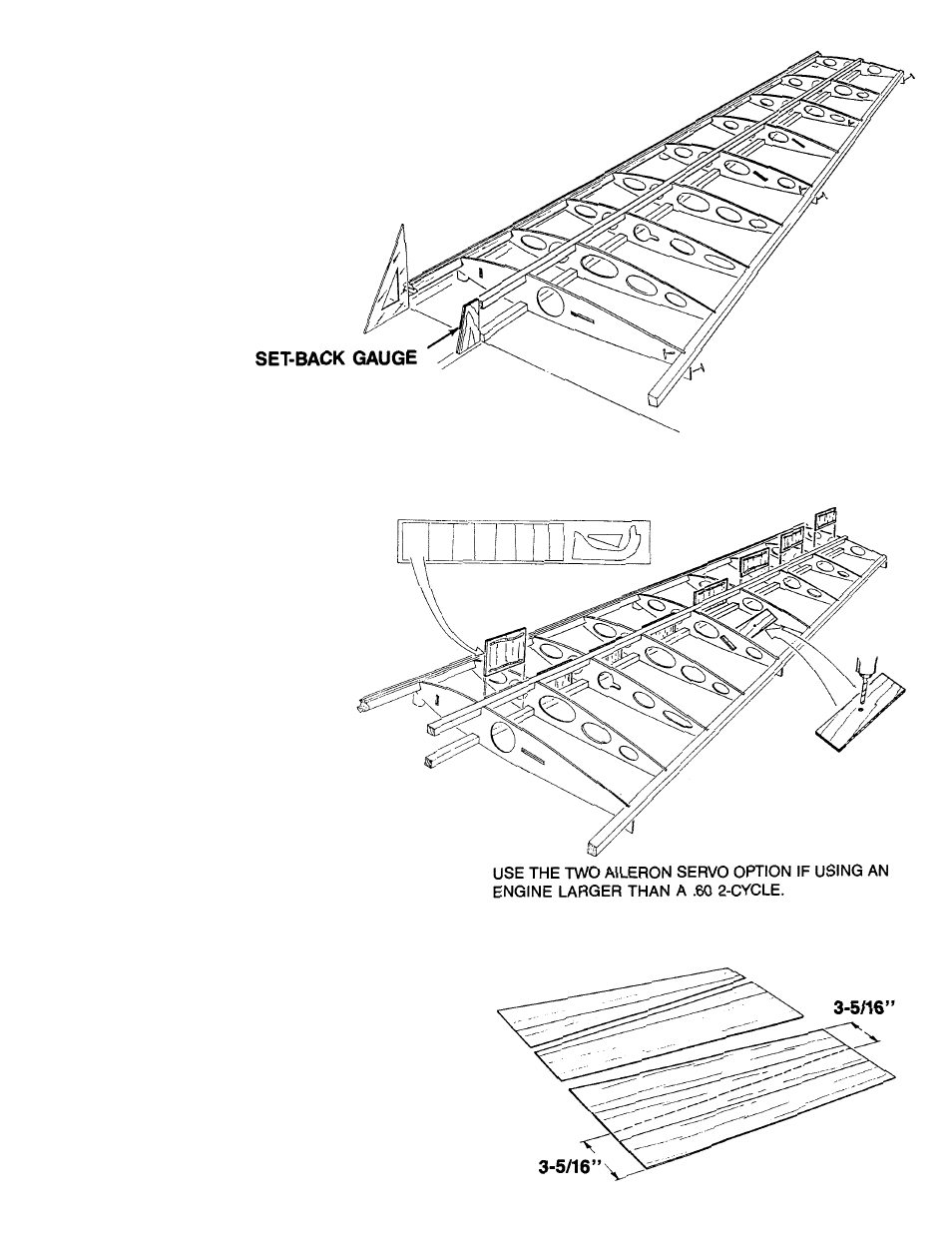
Using the set-back gauge for correct positioning, gently
slide the top spar into the rib notches.
■
■
Check the wing alignment with the plan underneath.
Then, place a drop of Jet glue at each joint along the
Leading Edge, the Spar, and the Trailing Edge.
9.
■
■
Glue the balsa shear webs to the
front side of the spars, centering the
shear webs between the wing ribs.
NOTE:
IF YOU ARE USING THE TWO-AILERON SERVO
SYSTEM, OMIT THE FOLLOWiNG.
■
■
Drill a 1/16” diameter hole at the center mark on each
of the aileron bellcrank supports and glue the support
between Ribs #6 and #7.
10.
■
■
Edge glue two sets of three 1/16 x 3 x 36” balsa sheets.
■
■
Measure 3-5/16” from opposite edges, as shown, and
mark.
■
■
Cut along the line established by the two marks. Repeat
this process on the other glued sheet. This gives you
the L.E. sheeting for the entire wing.