Two-servo system construction (6 steps) – Carl Goldberg GBGA0055 User Manual
Page 24
24
35.
■
■
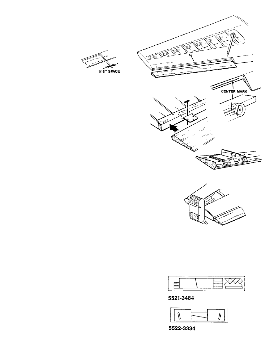
At this time, transfer hinge locations from the plan to
the ailerons. Next, transfer these marks to the wing. Be
sure to leave a 1/16” gap between the aileron and the
T.E. center section.
■
■
Use a CGM centerline tool and scribe a hinge
centerline into both ailerons and wing halves.
■
■
Hinge the ailerons just like you did the elevator and
rudder
■
■
Bevel the ailerons to the center scribe line, using the
bevel tool marked “AE.”
■
■
Temporarily hinge the ailerons to the wing to test the
fit. Then, sand the aileron to the tip plane of the wing.
NOTE:
Permanent assembly of the ailerons to the wings,
as well as control horn installation, is done after
covering.
IF YOU ARE INSTALLING ONLY ONE SERVO, THE WING
CONSTRUCTION IS NOW COMPLETE.
NOTE:
The two-servo option should be used for aircraft
using an engine larger than a .60 2-cycle.
1.
■
■
Collect the following parts needed to install an aileron
servo in each wing panel.
(1) D/C SHT. #5521 PLY
PT. #3484
CONTAINING SERVO MOUNTING PARTS
(1) D/C SHT. #5522 BALSA
PT. #3334
CONTAINING HATCH COVERS
(16) #2 x 5/16” SHT. METAL SCREW
PT. #1086
(16) #2 WASHER
PT. #1138
TWO-SERVO SYSTEM CONSTRUCTION (6 Steps)
TO BE INSTALLED ON A COMPLETED WING