Carl Goldberg GBGA0040 User Manual
Page 34
BATTERY PACK INSTALLATION
1. You must have fully charged nicads for flying.
2. Wrap the battery in 1/2” very soft foam rubber
to cushion it from vibration and shock. Use
rubber bands or tape to hold the foam around
the battery.
3. Position the battery in the fuse and hold it in
place with scrap 1/8” plywood , as shown on
the plan.
RADIO SWITCH AND CHARGING JACK
INSTALLATION
1. Position the radio switch (and optional charg-
ing jack) cover plates on the outside of the
fuse.
NOTE: In a 3-channel system installation, position
these plates on the side opposite the motor
servo.
Insert a pencil through the holes in the cover
plates, to mark the location of all holes and
openings.
2. Cut the necessary holes in the fuse side, mak-
ing sure the opening for the switch button is
long enough to allow the button to move to the
ON and OFF positions.
3. Referring to your radio equipment instructions,
install the switch and the charging jack in the
side of the fuse. Since the Electra is frequently
hand-launched, we prefer to install the switch
with the ON position toward the rear of the
model.
Later, when the radio is operational, identify
the ON and OFF positions with the decals pro-
vided.
RECEIVER (Rx) INSTALLATION
NOTE: Do not cut, shorten or store inside the fuse-
lage the antenna wire attached to the
receiver. This will greatly reduce the range
of the radio.
1. Connect all servo wires to the receiver, so that
the radio system is operational. Be sure that
each servo is plugged into its respective Rx
terminal.
2. Wrap the Rx in foam, as was done for the bat-
tery. Again, keep the Rx firmly in position with
scrap plywood.
3. Temporarily tape the antenna wire to the string
that was previously threaded through the fuse-
lage. Then, use the string to gently pull the
antenna out the rear opening of the fuse.
4. Gather together all excess lengths of servo
wires and tape down.
5. Apply ON/OFF decals to the outside of the
fuse at the switch location.
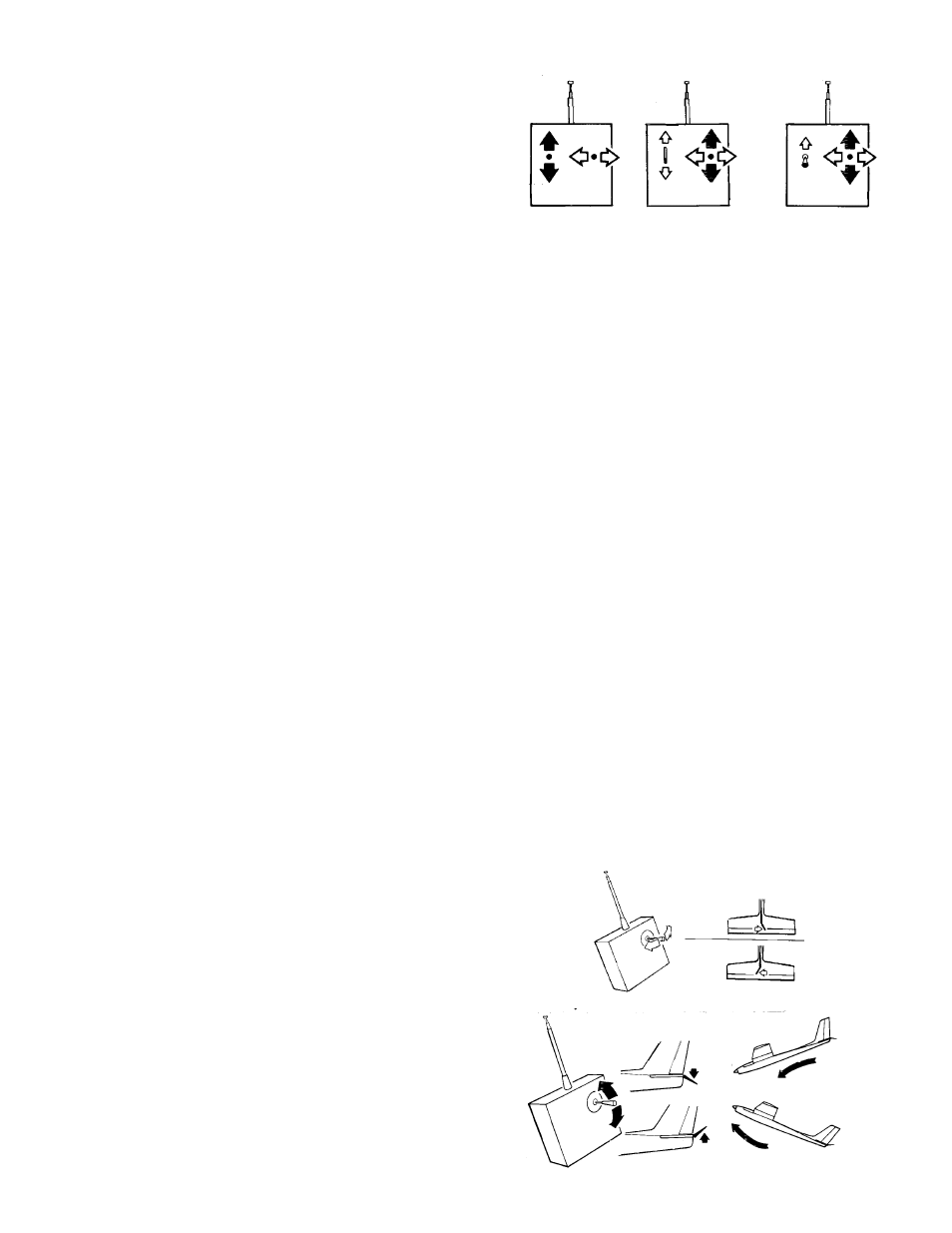
1. First read and follow the instructions that came
with your radio. The above sketches illustrate
the basic configuration of most transmitters.
Move the transmitter controls and observe
which servo wheels move when the stick is
moved for various controls.
2. Apply tape (which can be written upon) to each
servo and identify each for its control function:
“R” for rudder, “E” for elevator, etc. Mark the
plug for each servo the same way. If your Rx
does not have separate plugs for each servo,
but instead has places for the servos to plug
in, apply the tape mark nearby.
NOTE: As mentioned earlier in this book, radios with
the “servo reversing” feature greatly simplifies radio
installation because they allow the pushrods to be
hooked up to either side of the servo’s output wheel.
Then, after checking the control response, a servo
responding in the wrong direction is easily switched to
correct the action (see radio manufacturer’s instruc-
tions for me detail).
3. Push the transmitter motor lever up away from
you and observe where the motor servo wheel
should connect to the motor pushrod to move
the motor switch to the ON position. Mark this
on the servo wheel and then return the motor
lever to the full down (OFF) position.
Study the diagrams below to gain an understanding of
the various Tx functions and the effects they have on
the aircraft.
2-CHANNEL
2 STICKS CONTROL
2 SERVOS
3-CHANNEL
1 STICK AND 1 SLID-
ING TAB OR BUTTON
CONTROL 3 SERVOS
4-CHANNEL (OR MORE)
2 STICKS WHICH MAY
BE USED TO CONTROL
3 OR MORE SERVOS
SERVO MOVEMENTS
34