Carl Goldberg GBGA0040 User Manual
Page 24
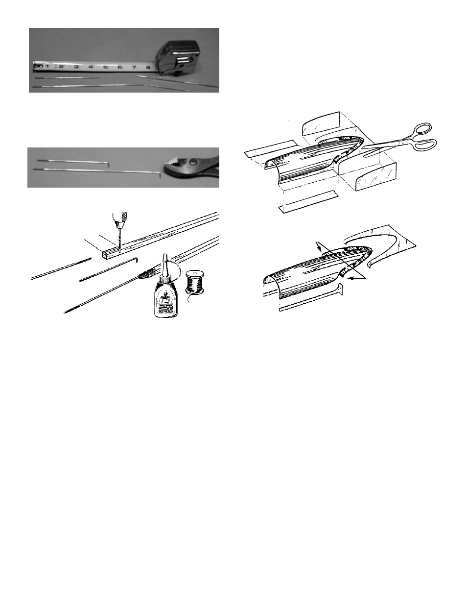
As was done with the threaded wires, bend
down one end of each 4” wire.
Again, make a recess in the wood and drill a
hole at the end of the recess to accept the
hooked end of the wire.
Attach each wire to the other end of each balsa
pushrod and secure, as before.
23. Remove the canopy from its vac-formed sheet-
ing by carefully cutting along the trim lines, as
shown above.
THIS COMPLETE THE CONSTRUCTION OF THE
FUSELAGE. IT IS NOW TIME TO TAKE ALL OF THE
MODEL COMPONENTS AND COVER THEM.
19. Take one of the two 10” threaded rods and
mark 7-1/4” from the threaded end. Cut at the
mark.
Take the other threaded rod and cut to a length
of 4-1/4”.
On each of the rods, bend the cut down about
1/4”, as shown.
20. Using the threaded end of one of the rods, file
a slight recess 1” long at one end of each 1/4”
sq. x 17-7/8” balsa pushrod.
Drill a 1/16” diameter x 1/4” deep hole at the
end of the recess in both pushrods.
Glue the threaded rods into the balsa pushrods,
as shown.
When the assembly is dry, taper (by sanding)
and round the balsa ends of each pushrod
where it meets the threaded rod.
Bind the rod/balsa joint with strong thread, coat
with Super Jet™, and allow to dry.
21. Referring to the full-size drawings on the plan.
take the shorter (rudder) pushrod with the 7”
wire attached and trim the balsa end so that the
entire balsa piece measures 12”.
Place the threaded wire over the fuse side
drawing on the plan and bend the wire to match
the plan.
NOTE: Leave the balsa on the other pushrod at its orig-
inal length, approximately 17-7/8”.
22. Take the 1/16 x 12” unthreaded wire rod and cut
into two 4” pieces. Save the scrap wire for the
radio installation.
24
FIRST REMOVE SIDE &
BOTTOM SCRAP
SECOND, CUT HERE.
THEN, CAREFULLY
TRIM AS SHOWN.