Removable tip option – Carl Goldberg GBGA0040 User Manual
Page 15
REMOVABLE TIP OPTION
NOTE: The materials needed to make the wing tip
removable are NOT INCLUDED in your kit.
Necessary templates for this option are found in
the upper right corner of the wing half of the plan.
Follow these steps ONLY IF YOU WANT TO BE
ABLE TO REMOVE THE WING TIPS. Otherwise,
continue at Step 14.
A. Collect the following items:
1/8” x 3” x 18” HARD BALSA SHEET
3/32” x 12” MUSIC WIRE
3/32 I.D. x 6” BRASS TUBE
3/34” VINYL ELECTRICAL TAPE
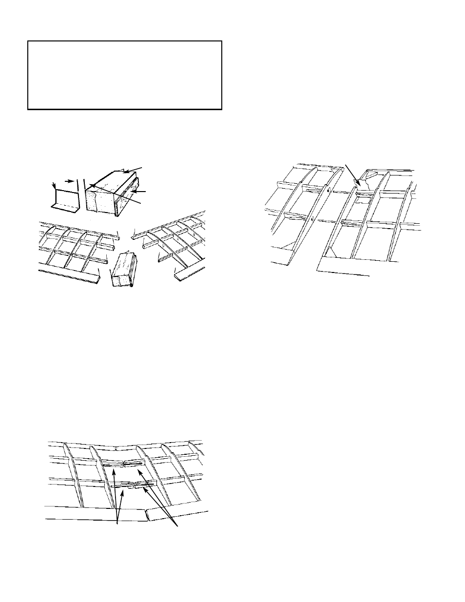
B. Make a sanding block from 1/8” scrap plywood,
using the SANDING ANGLE TEMPLATE from
the plan. Make sure to establish tthe proper
sanding block angle, as show above.
C. From the 1/8” hard balsa sheet, cut four NEW
#6 ribs. DO NOT USE THE #6 die cut ribs that
are included with your kit.
D. Remove the pins from the inboard panel and
use the sanding block to gently sand the poly-
hedral ends of the spars, the L.E., and the T.E.
to insure uniform vertical surfaces.
E. Referring to Step 14 for correct use of the die-
cut wing gauges, raise the inboard wing panel,
as shown.
F. Position the 3/32 x 3” wire on the back of the
spars, as shown.
Referring to the TIP OPTION on the plan, care-
fully groove the spars for the wire and for the
brass tube.
G. Tack-glue the WIRE to the OUTBOARD SPAR
and the BRASS TUBE to the INBROARD
SPAR.
Plug the wing panels together and make cer-
tain the wing structures butt evenly at the poly-
hedral joint. If adjustments are needed, take
the panels apart and rework the grooves slight-
ly.
When satisfied with the fit of the joint, glue the
metal parts in place.
H. With the wing panels plugged together, posi-
tion the new #6 ribs at the polyhedral joint. The
ribs should be tilted slightly toward the out-
board panel, so that they match the spar angle.
TAKING CARE TO NOT GLUE THE WING
PANELS TOGETHER, carefully glue the ribs to
their respective wing panels.
I.
Unplug the wing panels. Then, working on first
the inboard panel and then the outboard panel,
wrap a about 2” of 3/4” wide nylon fabric
(included in your kit) around each of the spars
to secure the wire and brass tubing.
Saturate the nylon fabric with Super Jet or Jet
Epoxy, to create a sturdy bond.
J. Add gussets (D/C Sht. 4006) at the L.E. and
T.E., as shown above.
NOTE: This completes the removable tip option con-
struction for the first wing half. When working on the
second wing half, you again will follow the above
instructions. After the wing parts are covered, the
removable panels are fastened to the inboard wing
sections using vinyl electrical tape. This tape holds
firmly, yet can be removed without damaging the cov-
ering material.
NOW PROCEED DIRECTLY TO STEP 19.
15
SANDING
BLOCK
SANDING
ANGLE TEM-
PLATE
POSITION & GLUE
SCRAP PLY TO BACK SO
THAT FRON MATCHES
WITH TEMPLATE.
3/32” I.D. TUBE
3/32” WIRE
WRAP NYLON AROUND SPARS,
TUBES, AND WIRES