Carl Goldberg GBGA0040 User Manual
Page 16
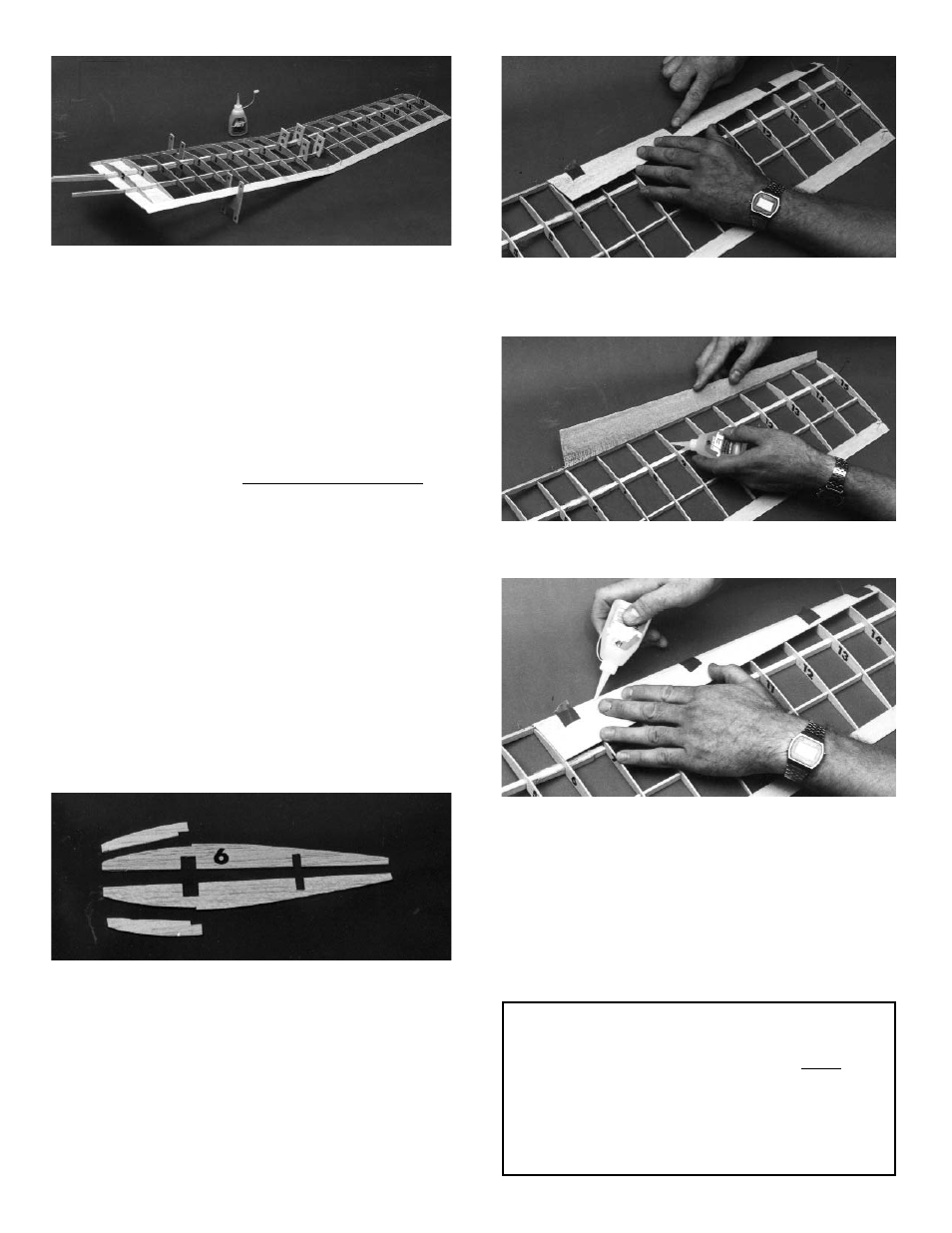
19. Set the outboard L.E. sheeting in place, aligning
the inboard edge of the sheet with the joint
between rib #6 and the #6a doubler. When cor-
rectly positioned, tape the sheeting to the L.E.
Lift the sheeting, as shown, and apply Super
Jet™ along the top of each rib where it will
contact the sheeting.
Fold the sheeting back down over the ribs and
hold in place until dry.
Apply a bead of glue to the L.E./sheeting joint,
in the areas between the tape. Allow to dry.
HINT: Using Jet Set™ accelerant speeds this (and
many other) gluing processes.
When the joint is firm, remove the tape and
apply glue to the remaining unglued areas of
the joint.
If this is your first wing half, set it aside and begin
building the left half of the wing.
MAKE SURE YOU WORK OVER THE LEFT WING
PORTION OF THE PLAN. DO ONLY STEPS 1
THROUGH 5 AND 10 THROUGH 19 FOR THE LEFT
INBOARD PANEL.
When both halves are complete to this point, con-
tinue with Step 20.
14. With the outboard panel still pinned down, raise
the inboard panel and support it with the wing
dihedral gauges under the first rib #5 location, as
shown on the plan.
IMPORTANT: The end of the gauge stamped “A” must
be up. Hold the gauges firmly in place by tack-cement-
ing, clothespins, etc.
Carefully inspect the panel joint to make sure all
of the end pieces of the inboard panel fit tightly
to those of the outboard panel. If one part pro-
trudes too much, sand slightly for a better fit.
WARNING: always sand just a little at a time, so
that you do not remove too much wood. You may
find it helpful to use the sanding tool described in
the removable tip option.
15. TEMPORARILY install the diihedral joiners on
each side of the spars. Use die-cut clampls to
hold in place.
When satisfied with the fit of the inboard and out-
board panels, pin in place, as shown above.
16. Remove the dihedral joiners and apply a liberal
bead of Super Jet to all joints of the L.E., spars,
and T.E.
Quickly apply glue to the joiners and immediate-
ly reinstall. Use the clamps again to hold both
joiners tight to the spars. Allow to dry.
17. Lay out two #6 ribs, and two doublers, as shown.
Glue rib doubler #6a to each rib, taking care to
make on left and one right rib.
18. Position rib #6 so that it aligns with the joints in
the L.E., the spars, and the T.E. Make sure that
the doubler is facing out, toward the outboard
pannel. When satisfied with the fit, glue in place.
Referring to the plan for location, glue gussets to
rib #6, the L.E., and the T.E.
16