Final assembly – Carl Goldberg GBGA0040 User Manual
Page 27
Apply covering to the solid bottom pieces, wrapping
and sealing around the edges. If necessary, slit the
corners for a smooth appearance.Apply covering to
the sides next, and then to the top. Make sure to over-
lap seams at least ¼”, so that when high heat is
applied, the shrinking will not create a gap.
Cover the hatch bottom, carefully sealing around the
edges. Trim the covering even with the hatch bottom
and remove the covering from the ventilation holes.
When covering the top of the fuse, do not cover the
stap platform, as proper installation of the stab requires
a wood-to-wood bond.
To minimize abrasion in landing, triple-cover the under-
side of the fuse from the nose to about 6” back.
Finally, it’s a very good idea to permanently affix your
name, address, phone number, AMA number and the
word “REWARD” on your aircraft. Then, if your model
should fly away for any reason, you’ll have a chance
of getiing it back.
Clean the model surfaces thoroughly before applying
decals.
Cut the decal sheet into sections, as needed. Fold the
decal in half, front to rear. Then open at the fold and
lay the decal out flat. The protective backing will bub-
ble away from the decal at the fold location.Using a
scissors, cut the backing along the bubble, removing
about a 1” wide strip of backing. Carefully position the
decal on the model and, working from the center out,
rub the decal down while peeling off the backing.
APPLYING DECALS
FINAL ASSEMBLY
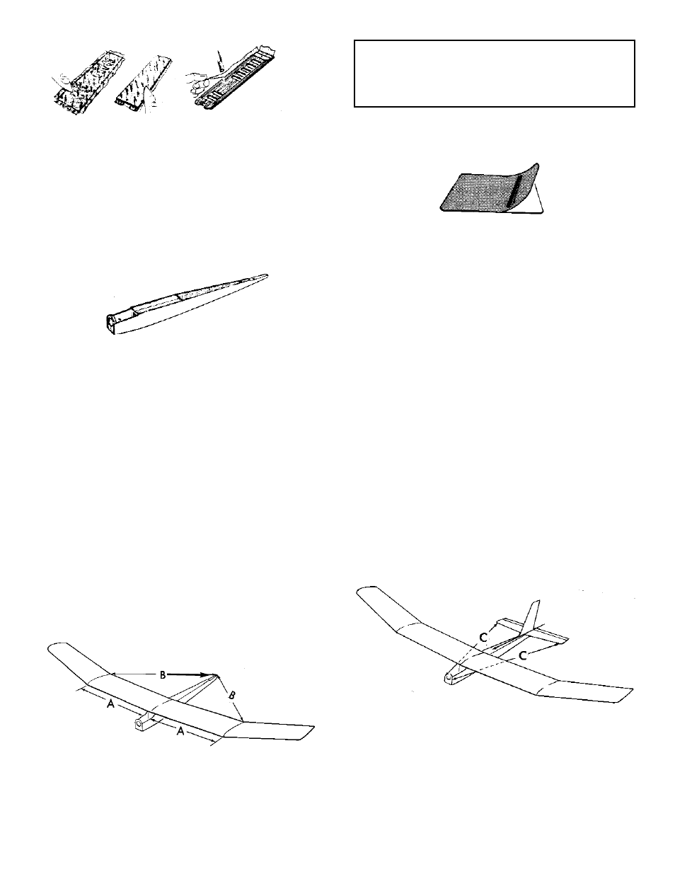
1. Gather the various covered elements of the
model, as well as the wing dowels and, if you
choose, any materials for the landing wheel
option.
2. Position the wing dowels so that they protrude
equally out of both sides of the fuse. Glue in
place and allow to dry.
3. Using #64 rubber bands (at least 6 on each
side of the fuse), mount the wing onto the fuse.
square with the fuse.
Using a piece of striping tape or a marking pen,
mark both the wing and the fuse with matching
line-up points, so that you will know where to
set the wing.
4. Measure carefully from the fuse sides to the
polyhedral breaks (“A” arrows), making sure
the wing is centered.
Next, measure from the polyhedral joints to the
back end of the fuse, making sure the wing is
5. Using no glue, trial fit the stab in place, adjust-
ing as necessary to line it up with the wing.
Measure from the stab tips to the fuse front
(“C” lines) to make sure the stab is square with
the fuse.
As was done with the wing, mark match-up
lines on the fuse and stab. Draw a line from the
stab L.E. marks to the stab T.E. marks.
27