Carl Goldberg GBGA0040 User Manual
Page 23
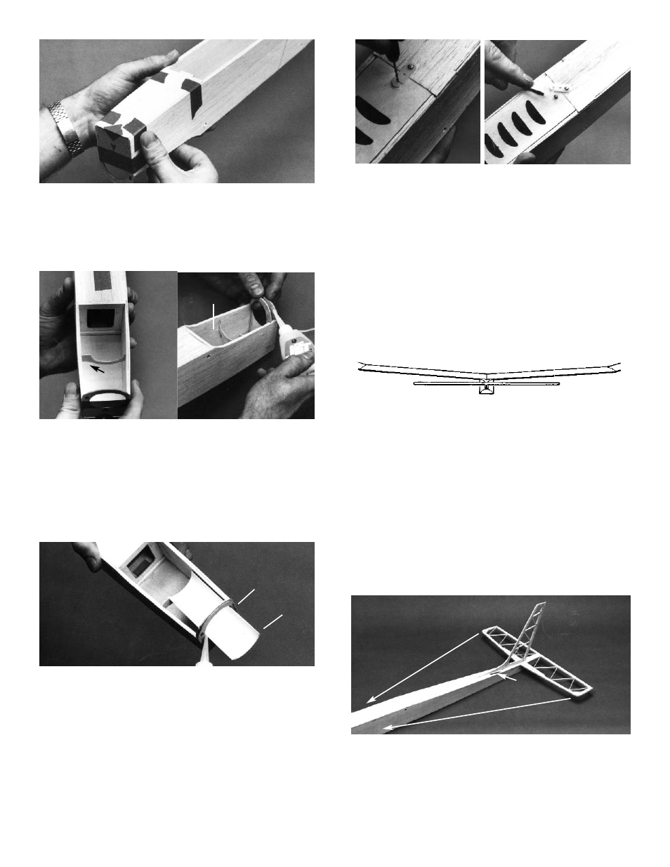
13. Turn the fuse over and position the 1/16” ply
front bottom sheet on the fuse sides, behind
Former “A.”
Tape the sheet in position and then glue the
joints. When dry, remove the tape and apply
the glue to the taped areas.
14. Referring to the plan, spread the fuse sides
slightly and insert the motor mount support into
the notches. IMPORTANT! The side stamped
“R” must be positioned on the right side of the
model.
Glue the motor mount support in place.
Then, insert and glue the two Former “A” dou-
blers in place behind Former “A.”
16. Place the battery hatch in the fuse bottom and
position a nylon flat hold-down at the centerline
of the fuse. The open-hole half of the fastener
should rest on the battery hatch and the close-
hole half on the fuse rear bottom sheet.
Mark the fastener hole locations with a pencil.
Using a 1/16” drill bit, first install the hold-down
on the fuse bottom sheet with a #2 x 3/16”
sheet metal screw.
Install the #2x 3/16” shoulder screw with
enough of the unthreaded shaft exposed to
engage the fastener. Test for fit.
15. Position the plastic motor mount so that
approximately 1-1/2” protrudes in from of
Former “A.”
Using either Super Jet™ or Jet Epoxy, glue to
Former “A” and the rear motor mount. Allow to
dry.
NOTE: The motor mount is offset to compensate for
motor torque and to help the plane fly straight.
17. Temporarily install the wing dowels in the fuse.
Rubberband the wing onto the fuse, making sure
it is centered and level.
Trial fit the stab in place, determining whether or
not it sits level with respect to the wing.
If necessary, sand the stab platform to provide a
good, level fit for the stab. DO NOT ALTER THE
DIE-CUT ANGLE OF THE FUSE SIDES!
Center the stab on the fuse. Measure from the
stab leading edge to the front of the fuse to make
sure the stab is exactly centered.
When satisfied with the fit, pin in place.
18. Glue the dorsal fin to the main fin. When dry,
carefully trim off the die-cut bumps.
Trial fit the fin assembly onto the stab. DO NOT
GLUE. Sand as necessary to obtain a good fit.
23
1-1/2”
FOR GEARED
MOTORS USE
LOWER SLOT
R TOWARD
RIGHT
LEVEL STAB WITH RESPECT TO WING
EQUAL DISTANCE
FROM STAB TIP TO
NOSE
DORSAL FIN