Carl Goldberg GBGA0040 User Manual
Page 30
NOTE: When handling the motor and switch harness,
try to avoid bending the wires near the soldered con-
nections. If handled carelessly, these joints can be bro-
ken.
The following instructions are for installing the Turbo
550 motor. If using another motor, you may need to
modify the installation according to the motor manu-
facturer’s instructions.
IF USING A 2-CHANNEL INSTALLATION, PRO-
CEED TO STEP 4 and return to the fuselage side
view on the plan for switch location..
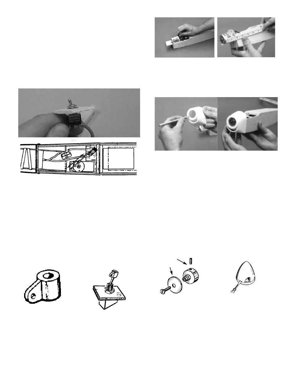
1. For a 3-channel installation, remove the lock
washer and nut from the top of the switch and
insert the ply mounting plate, as shown.
2. Locate switch mount just forward of former “B”
and about 1/2” below the top edge of the fuse
side. Refer to the top and side views on the
plan.
NOTE: The motor switch body must be turned, so the
switching action aligns with the pushrod from the motor
servo.
When satisfied with the position, glue the
switch mount to the fuse side and former “B”.
4. Insert the motor through from the rear of
Former “A”, so that the motor front protrudes
about 1-3/4” out from the front of the fuse. Hold
the motor in its mount, using rubber bands.
For 2-channel only, drill or cut a 1/4” dia. hole
through the fuse side and mount the switch.
5. Using a scissors, carefully remove excess
plastic from the base of the cowl.
Using a sharp hobby knife, rather than the scis-
sors, cut motor and vent holes. Do not try to
“force” the knife, since it could slip and damage
either the part or you. Instead, make a series
of light cuts, each a little deeper than the last.
6. Referring to the fuse side view on the plan for
the location of the screws, mark the location of
the screws and drill four 1/16” holes through
the cowl.
Set the canopy in place on the fuse and then
position the cowl over the fuse front and the
canopy.
When satisfied with the fit, screw the cowl in
place.
6. Thread a #4 socket set screw in the prop
mount and turn a few times.
Open the spinner supplied by carefully insert-
ing a small screwdriver straight into each of the
slots. DO NOT TWIST! JUST PRY OPEN.
NOTE: Carefully read the instructions included with
your spinner. Rehydrating of the plastic will
make it easier to open and close the spinner .
When the spinner backplate has been
removed, place it on the propeller mount.
FUSE TOP VIEW
3. Using a 7/64” drill, enlarge the nylon bracket to
fit snugly on the switch. You may need a mod-
eling knife to make the hole slightly larger than
7/64”.
With the bracket flange parllel to the switching
action, glue the bracket to the switch.
30
#4 SET SCRES
LARGE WASHER