Figure 6.15, Figure 6.16, Manifold nut and bolt locations – AERCO KC1000 Heater Mar 2011 User Manual
Page 55: Maintenance
MAINTENANCE
6-11
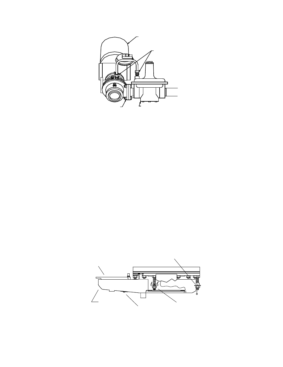
AIR/FUEL
VALVE
COMPRESSION
FITTINGS
DIFFERENTIAL PRESS.
REGULATOR
3/8 - 16
HEX NUT/BOLT
Figure 6.15
Feedback Tube and Air/Fuel Valve to Differential Regulator Bolts
22. Remove the flue venting from the exhaust manifold.
23. To prevent damage and simplify handling of the exhaust manifold, it will be necessary to remove the
exhaust manifold insulation. Using a 7/16” wrench or socket, remove the 3 bolts and fender washers
securing the insulation to the exhaust manifold (Figure 6.16).
24. Loosen the three 1-1/16” nuts that hold the manifold. Remove the two side nuts
. DO NOT REMOVE
THE FRONT NUT (Figure 7.8).
25. Carefully pull the manifold down and back, removing it through the back of the unit.
26. Inspect the manifold and exhaust tubes for debris. Clean out any debris as necessary.
27. Inspect the combustion chamber and liner. Replace the liner if any signs of cracking or warping are
observed.
NOTE:
The combustion chamber liner should be installed prior to reinstalling the
exhaust manifold.
SIDE NUT
(1 EACH SIDE)
FRONT NUT
(DO NOT REMOVE)
EXHAUST
MANIFOLD
INSULATION
7/16" HEX HEAD
& FENDER WASHER
(3 PLACES)
Figure 6.16
Manifold Nut and Bolt Locations