Start/stop levels, Control panel operating procedures – AERCO KC1000 Heater Mar 2011 User Manual
Page 27
CONTROL PANEL OPERATING PROCEDURES
3-9
154
155
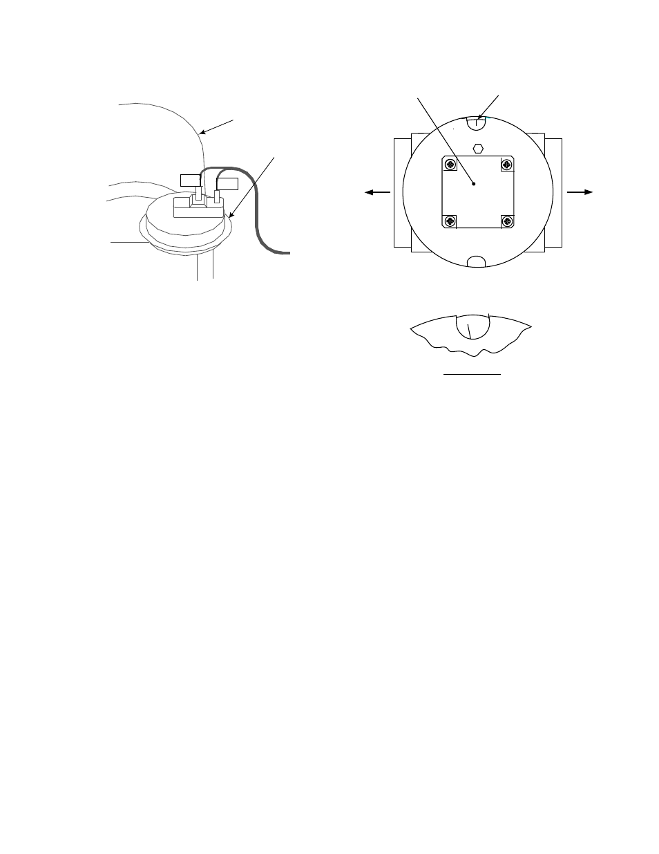
AIR/FUEL VALVE
BLOWER PROOF
SWITCH
TO FRAME
HARNESS
Figure 3-5.
Blower Proof Switch
5. Upon completion of the purge cycle, the
Control Box initiates an ignition cycle and the
following events occur:
(a) The Air/Fuel Valve rotates to the low-fire
ignition position and closes the ignition
switch. The dial on the Air/Fuel Valve
(Figure 3-6) will read between 25 and 35
to indicate that the valve is in the low-
fire position.
(b) The igniter relay is activated and pro-
vides ignition spark.
(c) The gas Safety Shut Off Valve (SSOV)
is energized (opened) allowing gas to
flow into the Air/Fuel Valve.
6. Up to 7 seconds will be allowed for ignition to
be detected. The igniter relay will be turned
off one second after flame is detected.
7. After 2 seconds of continuous flame, Flame
Proven
will be displayed and the flame
strength will be indicated. After 5 seconds,
the current date and time will be displayed in
place of the flame strength.
8. With the unit firing properly, it will be
controlled by the temperature controller cir-
cuitry. The
VALVE POSITION will be
continuously displayed on the front panel
bargraph.
9.
STEPPER
MOTOR
DETAIL "A"
DIAL
(DETAIL “A”)
BL
O
W
E
R
BU
R
N
ER
25
Figure 3-6.
Air/Fuel Valve In Ignition Position
10. Once the demand for hot water has been
satisfied, the Control Box will turn off the gas
valve. The blower relay will be deactivated
and the Air/Fuel Valve will be closed.
Standby will be displayed.
3.9. START/STOP LEVELS
The start and stop levels are the valve position
percentages that start and stop the unit, based
on load. These levels are Factory preset as
follows for natural gas and propane units:
•
Start Level:
20% (All units)
•
Stop Level:
13% (Natural Gas)
•
Stop Level:
16% (Propane)
Normally, these settings should not require
adjustment.
Note that the energy input of the water heater is
not linearly related to the fire rate percentage
(Air/Fuel Valve position). Refer to Table 3-6 for
the relationship between the energy input and
Air/Fuel Valve position (% open) for a unit
running on natural gas.