Figure 6.10, Grounding terminal location, Maintenance – AERCO KC1000 Heater Mar 2011 User Manual
Page 52
MAINTENANCE
6-8
The following parts will be necessary for reassembly after inspection:
GP-122537
Exhaust Manifold to
Combustion Chamber
Gasket
GP-18900
Manifold to Tubesheet
Gasket
124749
Lower Burner Gasket
124834
Upper Burner Gasket
*124839
Combustion Chamber Liner
*Not necessary to change but should be on hand in the event damage occurs during the inspection.
To remove the manifold for inspection:
1. Disconnect AC power and turn off the gas supply to the unit.
2. Remove the sheet metal covers from the unit.
3. Disconnect the plastic tubing from the condensate cup to drain and remove the rear covers.
4. Remove the condensate cup from under the unit and the condensate drainage tubing from the
manifold.
5. Disconnect the flame detector and ignition cable wires from the flame detector and igniter contactor.
Remove the flame detector and igniter as per paragraphs 6.2, and 6.3.
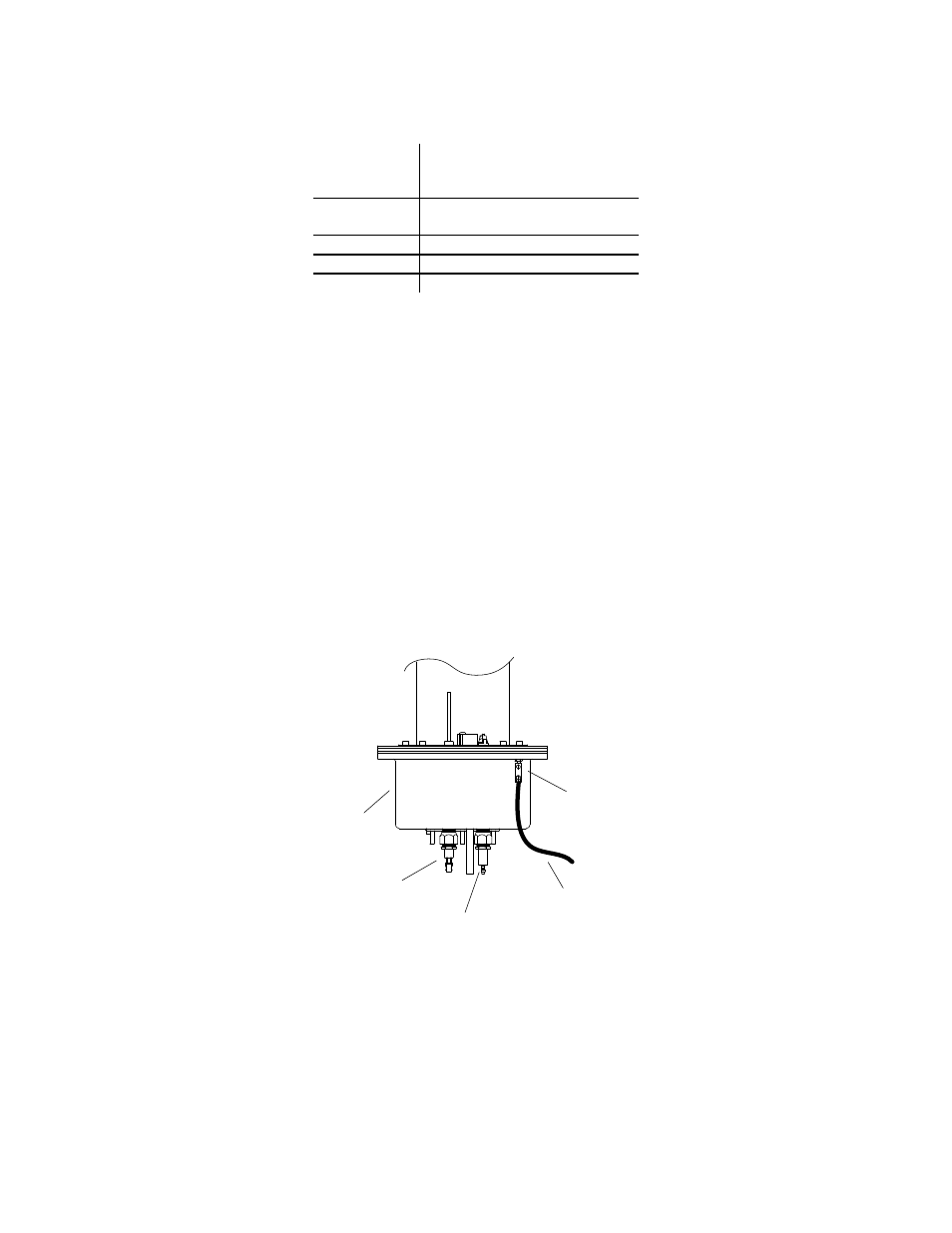
6. Remove the grounding terminal from the burner by loosening the upper screw and sliding the
connector from the grounding rod, (See Figure 6.10).
GROUND
TERMINAL
UPPER
SCREW
LOWER
BURNER
SHELL
FLAME
DETECTOR
IGNITER
GND WIRE FROM
TRANSFORMER
Figure 6.10
Grounding Terminal Location
7. Loosen the 1/4” NPT union on the low NOx staged ignition assembly (Figure 6.11).
8. Disconnect the staged ignition assembly 1/8” elbow from the 3” long NPT nipple at the bottom of the
burner shell.
9. Remove the 3” long NPT nipple and 1/4” O.D. tube (Figure 6.11) from the burner shell.