3 installation, 1 setting the unit, Figure 2.2 – AERCO KC1000 Heater Mar 2011 User Manual
Page 10: Lifting lug location, 2 water inlet and outlet piping, Installation
INSTALLATION
2-2
2.3 INSTALLATION
The unit must be installed with the prescribed
clearances for service as shown in Figure 2.1.
These are the minimum clearance dimensions
required by AERCO. Local building codes may
require more clearance and take precedence.
WARNING !
KEEP UNIT AREA CLEAR AND FREE
FROM COMBUSTIBLE MATERIALS AND
FLAMMABLE VAPORS AND LIQUIDS
.
MASSACHUSSETTS INSTALLATIONS
For water heater installations within the
Commonwealth of Massachusetts, the heater
must be installed by a plumber or a gas fitter
who is licensed within the Commonwealth. In
addition, the installation must comply with all
requirements specified in Section 1 (Safety
Precautions), pages 1-2 to 1-4.
2.3.1 SETTING THE UNIT
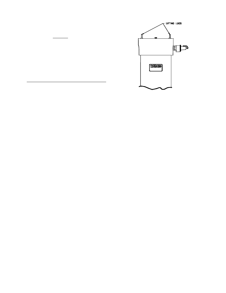
Locate the lifting lugs, shipped with the unit, and
attach them to the 5/8” x 11 studs at the top of
the unit. Remove the unit from the wooden skid
and place in position using a block and tackle or
hoist attached to the lifting lugs (Figure 2.2).
USE THE LIFTING LUGS TO MOVE THE
UNIT.
The KC-1000 is U/L approved for installation on
combustible flooring. A 4 to 6 inch high house-
keeping concrete pad is recommended and
allows for sufficient drainage of the condensate.
The unit must be secured using only the holes
provided in the frame base. Do not use piping to
secure the unit in place. See drawing AP-A-804
in Appendix E for the base frame dimensions.
In multiple unit installations, it is important to
plan the position of each unit. Sufficient space
for piping connections and maintenance require-
ments must be given. All piping must include
ample provision for expansion
.
Figure 2.2
Lifting Lug Location
3
2.3.2 WATER INLET AND OUTLET
PIPING
The locations of the 2" NPT cold water inlet and
hot water outlet piping connections are shown in
Figure 2.3. Flow rates through the unit are
limited to 30 gpm continuous and 40 gpm
intermittent.
The heater is shipped with a 2” NPT x 12” long
stainless steel flex connector. It is important that
this flex connector be installed at the hot water
outlet as mentioned in the installation diagrams
to ensure compliance with the AERCO warranty.
If it is desired to install the flex connector
elbowed towards the rear or top of the unit, two
additional parts (not supplied with heater) are
required. These parts are a 2”NPT x 6” long 304
or 316 stainless nipple and a 2” NPT 304 or 316
stainless elbow. Both of these parts must be
capable of withstanding up to 155 psig @ 210°F.
These parts may be added between the heater
outlet connection and the flex connector.
However, if this heater was ordered with the
optional copper-lined carbon steel shell (contact
your local AERCO Representative to verify), it is
not shipped with, and does not require a flex
connector.