Figure 6.11, Burner disassembly diagram, Figure 6.12 – AERCO KC1000 Heater Mar 2011 User Manual
Page 53: Exhaust sensor connector location, Maintenance
MAINTENANCE
6-9
10. Using a 7/16” socket or open end wrench, remove the four 1/4-20 nuts on the gas inlet pipe flange at
the burner.
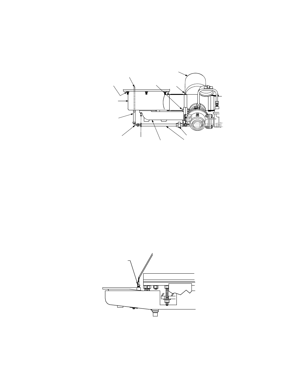
LOW NOx
BURNER
SHELL
STAGED IGNITION
ASSEMBLY
1/8" STREET
ELBOW
1/8" NPT
NIPPLE
3" LONG
1 /4-20
HEX NUTS
(4)
GAS INLET
PIPE
HOSE
CLAMP
AIR/FUEL
VALVE
5/16-18
HEX NUTS (6)
3/8-16 HEX
NUTS &
BOLTS (2)
1/4" NPT UNION
1/4" O.D.
TUBE
Figure 6.11
Burner Disassembly Diagram
11. Using two 9/16” wrenches, remove the two 3/8-16 hex nuts and bolts on the gas inlet pipe flange at
the air/fuel valve (Figure 7.3). Remove the gas inlet pipe.
12. Loosen the hose clamp on the air/fuel valve outlet (Figure 6-11)
13. Using a 1/2” socket wrench, remove the six 5/16-18 hex nuts supporting the burner (Figure 6.11).
14. Lower the burner while sliding the air hose off the air/fuel valve. Remove the burner through the rear
of the unit. Due to space limitations, it will be necessary to separate the burner head and shell during
the removal process.
15. Disconnect the exhaust temperature sensor by unscrewing it from the exhaust manifold (Figure 6.12).
EXHAUST
TEMP.
SENSOR
Figure 6.12
Exhaust Sensor Connector Location
16. Disconnect the air/fuel valve 12-pin con-nector from the KC wiring harness.
17. Disconnect wires #24 and #17 from the blower proof switch (Figure 6.13).