C-more control panel operation – AERCO C-More Controls User Manual
Page 36
C-MORE CONTROL PANEL OPERATION
32
7. With the unit firing properly, it will be
controlled by the temperature controller
circuitry. The FIRE RATE will be
continuously displayed on the front panel
bargraph.
8. Once the demand for heat has been
satisfied, the Control Box will turn off the gas
valve. The blower relay will be deactivated
and the Air/Fuel Valve will be closed.
Standby
will be displayed.
DIAL
(DETAIL “A”)
STEPPER
MOTOR
DETAIL "A"
25
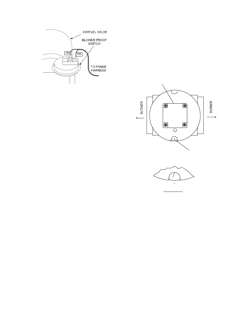
Figure 5-5.
Figure 5-4.
Blower Proof Switch
5. Upon completion of the purge cycle, the
Control Box initiates an ignition cycle and the
following events occur:
(a) The Air/Fuel Valve rotates to the low-fire
ignition position and closes the ignition
switch. The dial on the Air/Fuel Valve
(Figure 5-5) will read between 25 and 35
to indicate that the valve is in the low-
fire position.
(b) The igniter relay is activated and
provides ignition spark.
(c) The gas Safety Shut Off Valve (SSOV)
is energized (opened) allowing gas to
flow into the Air/Fuel Valve. Up to 7
seconds will be allowed for ignition to be
detected. The igniter relay will be turned
off one second after flame is detected.
6. After 2 seconds of continuous flame, Flame
Proven
will be displayed and the flame
strength will be indicated. After 5 seconds,
the current date and time will be displayed in
place of the flame strength.
KC1000 Air/Fuel Valve In Ignition Position